


MX80L Series Product Manual Chapter 3 - How to Use the MX80
Parker Hannifin Corporation
32
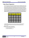
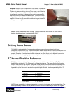
repeatability the final homing speed must be slow. Slower final speed usually results in higher
repeatability.
NOTE
: The “Z” channel output is only one resolution count wide. Thus the on-time may be very brief.
Due to this some controllers may have difficulty reading the signal. If you are experiencing the positioner
not finding the “Z” channel during homing, try reducing final homing speed; also refer to your controller
manual for frequency rates of the “Z” channel input.
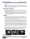
Grounding / Shielding
All cables are shielded. These shields are to be grounded to a good earth ground. Failure to ground
shields properly may cause electrical noise problems. These noise problems may result in positioning
errors and possible run away conditions.
The motor cable has an area of the shield exposed to allow a grounding path from shield to drive ground.
The Hall/Encoder and Limit/Home cables have the shield carried through the connector hood that is in
turn grounded through the drive. MX80L purchased with ViX drives as part of the configurable part
number come equipped with p-clips designed for the small OD of the motor cable to allow the cable
shield to be grounded to the ViX ground.
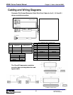
Cabling
The MX80L is provided with high flex cabling which is strain relieved at the connection point on the
positioner. The Hall/Encoder cable is terminated with a high density 15 pin D-sub connector which is
compatible with the ViX drive from Parker. The motor cable is terminated with flying leads which are
stripped and tinned and ready for installation into the screw terminals on the ViX drive. For wire color
codes and pin outs see tables in electrical section of manual.
The limit/home cable is optional and therefore if not ordered a space will be open in the clamp at the
connection point. The limit/home cable is provided with a 15 pin D-sub connector which is compatible
with the ViX drive. For wire color codes and pin outs see tables in electrical section of manual.
Recommended bend radius for these cables is 50mm. This radius will provide a minimum of 10 million
cycles of the cable. Smaller bend radius will reduce cable life while larger bend radius will increase life.
If the positioner is mounted in a multi-axis configuration special care should be taken in routing and strain
relieving the cables so as to prevent flexing of the cable at the connection to the table and where
mounted stationary to the structure. Provide sufficient service loop that the cable bends a minimum of
25mm from these end points. It is also recommended to avoid twisting the cable. The cable should be
secured in a position which will orient it in a direction that creates a single plane of operation for the
cable.
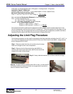
To replace extension cables 1.) Disconnect power to positioner. 2.) Remove two button head screws
from side of shield and remove the shield. 3.) Remove the two cap head screws from the strain relief
and remove the strain relief. 4.) unplug extension cables. 5.) Reverse steps to reassemble.
Note
: When reassembling the strain relief, take care not to pinch any wires and be certain that the
exposed braided shield on the cables lies under the strain relief.
Cable Management
Daedal Division
Irwin
,
Penns
y
lvania