


MX80L Series Product Manual Chapter 3 - How to Use the MX80
Parker Hannifin Corporation
29
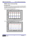
Limit and Home sensor operation
The MX80L utilizes an innovative method for setting limit and home positions. The magnetic sensors
embedded in the base of the MX80L change state based on the limit “flag”. This space saving, compact design
consists of three (3) parts; magnetic sensors, limit flag and limit flag bracket. The limit and home magnetic
sensors are mounted to a PCB in a fixed position to the base of the unit. The flag bracket is mounted to the left
side of the carriage with respect to the cables. The Limit Flag is a pattern of thin magnets which triggers the
sensors. This pattern defines whether the switch functions as normally open or normally closed. A limit is
normally closed when the switch operates from non-magnet to magnet surfaces. The home switch is normally
open when the switch operates from non-magnet to magnet surfaces. To change from normally open to
normally closed operation of the sensor the patterns are reversed.
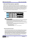
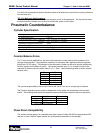
Example of Limit and Home Flag magnets corresponding to possible MX80L Limit Home configurations:
Config Home End of Travel Limit Flag Magnets
Normally
Closed
Normally
Closed
Normally
Closed
Normally
Open
Normally
Open
Normally
Closed
Normally
Open
Normally
Open
H1L1 Option Upgrades
• Limits and Homes can not be added to the MX80S table in the field due to the integrated design
which encloses the sensor on a printed circuit board in the base. If the magnetic sensor limit
and home are desired the unit must be returned to the factory on an RMA.
• To change Limit/Home operation from Normally Open to Normally Closed or from Normally
Closed to Normally Open a new limit flag bracket must be purchased, contact factory for proper
configuration and part number.
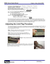
• To adjust the operating position of the limits, limit/home adjustment magnets can be adhered on
top of the existing limit flag. These adjustment magnets are included with the unit.
To change the activation position of the sensors:
Determine desired position
Cut magnet to proper length
Follow Adjusting Limit Flag Procedure to add to the adjustment
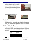
Determining Desired Position
The limit sensors are set at the factory for maximum travel. These factory settings only allow for 3mm
(0.12”) before the carriage contacts the end stop. In slow speed applications this may be adequate,
however as the top speed of the application increases the required deceleration distance increases. To
determine the safe Deceleration Distance the Maximum Speed and the Maximum Obtainable
Deceleration Rate must be known or calculated. The maximum speed should be known from your
application requirements. Velocity limits should be set in your program or in your amplifier to cause a
fault if the speed exceeds this value. The maximum deceleration is a factor of load and available peak
force of the table. Using F = ma, calculate maximum acceleration and then required deceleration
distance. See the following example for calculating maximum deceleration for an application with a
payload = 0.25 kg on an MX80-T01 with a maximum speed of 500 mm/s.
Daedal Division
Irwin
,
Penns
y
lvania