


Northstar M121/M84 Installation and Operation Manual92
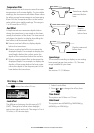
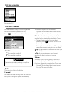
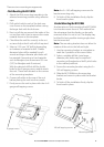
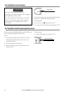
20-3 Installation: The display unit
Start by selecting a suitable mounting position
for the M121/M84 display unit:
• Consider the best possible position for
viewing and operating the M121/M84. This
will generally be a relatively shaded area free
from obstructions.
• At least 4” (100 mm) away from the compass,
at least 12” (300 mm) away from any radio
transmitter and at least 4 ft (1.2 m) away
from any antenna.
• For optimum performance and reliability
consider mounting the unit where it will not
be unnecessarily exposed to direct sunlight,
water and protected from other physical
damage which could occur during rough
sea passages.
• If bracket mounting chose a flat area where
the display will not be subjected excessive
vibration.
• Select an area with adequate clearance for
cabling and access to the power source.
• Before drilling any holes ensure that
the drill area is free from cables or other
obstructions.
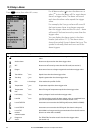
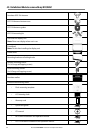
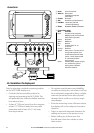
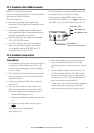
Connections
M121
q Sonar Sonar Transducer
w Video in Video Input
(Analogue composite
[NTSC-PAL])
e Comms Not Used
r GPS Northstar 124 GPS Antenna
t Fuel/Nav - Northstar Fuel TXD
- SmartCraft Gateway
y Radar Northstar Radar Processor
u
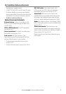
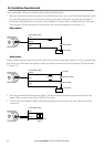
u Power/data cable
Wire Function
Black Ground: power negative,
NMEA ground (Connect both
black wires to ground)
Brown Not Used
White NMEA out
Blue NavBus-
Red Positive power in, 10
to 35 V DC
Orange NavBus+
Yellow Auto power - Connect to red
wire (positive power in) to
enable Auto power No Auto
power - Leave disconnected
or connected to Black
wire (ground)
Green External Alarm output or light
out, switches to ground
during alarm condition,
200 mA maximum.
71 2 3 4 5 6