


Please Give Part No., Description and Unit Serial No.
HIGHWAY EQUIPMENT COMPANY
28
97373-A
Page Rev. A
INSTALLATION INSTRUCTIONS CONTINUED
FENDER INSTALLATION
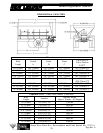
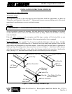
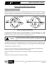
Figure 5 - Fender Angle Installation
Attach fender angles to
spreader body as shown
in Figure 5. Use upper
set of holes for full or
super floatation fenders
and lower set of holes for
semi-float and truck
chassis mount fenders.
Do not tighten hardware
at this time.
NOTE: Some fenders
have angles in place of
panels shown.
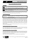
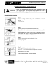
Attach fenders on top of
angles/panels as shown in
Figure 6. Tighten all
hardware.
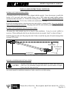
Figure 6 - Fender Installation
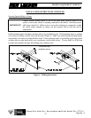
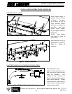
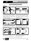
ELECTRIC DUMP VALVE CONTROL INSTALLATION
Figure 7 - Electric Dump Valve Control
Manual hydraulics only:
Splice wire from switch into wire
with two amp to four amp fuse
using tap connector. (See
location of tap connector in
Figure 7.) Ground ring terminal to
chain shield hardware. Mount
switch in dash or control panel in
a location that is easily accessible
while operating vehicle.