


Please Give Part No., Description and Unit Serial No.
HIGHWAY EQUIPMENT COMPANY
25
97373-A
Page Rev. A
INSTALLATION INSTRUCTIONS CONTINUED
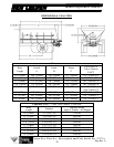
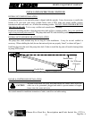
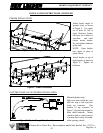
Positioning Body
Using a suitable lifting device, lift empty spreader onto truck frame. Position body centrally with respect to
truck frame rails and approximately 4" from rear of cab. Check position of spreader at rear to insure rear
mounting angle can be installed on truck frame and centered on rear cross tube.
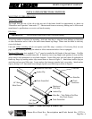
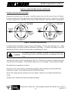
Installing Front Mounting Angles
Assemble two front mounting angle springs and hardware. Use a 3/8" shim between cross tube mounting
plate and truck frame mounting angle. Position assembly under second cross tube from front and against truck
frame, make sure springs do not contact cross tube. Mark position of mounting angle holes on truck frame.
Drill 9/16" holes where marked and install mounting assembly using 1/2" hardware supplied. Weld mounting
plate to bottom of cross tube on three sides, and remove 3/8" shim (Figure 4, page 27). Tighten spring
assembly until spring compressed height is 4". There should be a 3/8" space between cross tube mounting
plate and truck frame mounting angle (Figure 3, page 26). Repeat this procedure on other side of truck frame,
on same cross tube.
NOTE: It may be necessary to mount front mounting angle springs on first cross tube on some vehicles due to
obstructions such as spring shackles etc.
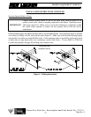
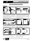
Installing Center Mounting Angles (10 Foot and 11 Foot Bodies)
Position center mounting angles at a convenient cross tube near center of body with slotted faces against truck
frame. Weld mounting angle to bottom of cross tube on three sides (Figure 4, page 27). Do not install
hardware, these mounting angles are for side to side support only (Figure 3, page 26).
Installing Center Mounting Angles (12 Foot to 16 Foot Bodies)
Position center mounting angles at a convenient cross tube near center of body with slotted faces against truck
frame and mark location of slots on truck frame. Drill 9/16” diameter holes through truck frame approximately
3/4” from bottom of slots (Figure 3). Weld mounting angle to bottom of cross tube on three sides (Figure 4).
Install hardware and tighten to recommended torque.
NOTE: Position of center mounting angles will vary due to obstructions such as spring shackles, etc.
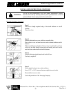
Use only lifting devices that meet or exceed OSHA standard 1910.184. Never
exceed work load limits or lift equipment over people. Empty spreader before
lifting. Loads may shift or fall if improperly supported, causing injury.
WARNING
Keep unit supported until mounting is complete. Unit could slip off chassis, causing
injury or damage to unit.
WARNING
IMPORTANT!
DO NOT PUT HOLES INTO TOP OR BOTTOM FLANGES—to do so may
void truck manufacturer’s warranty. When drilling holes in frame member, drill only
through vertical web portions.