


Please Give Part No., Description and Unit Serial No.
HIGHWAY EQUIPMENT COMPANY
23
97373-A
Page Rev. A
INSTALLATION INSTRUCTIONS CONTINUED
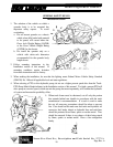
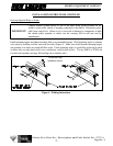
HYDRAULIC PUMP INSTALLATION
A mounting bracket for the hydraulic pump is shipped with the spreader. It may be necessary to modify this
bracket to fit your truck since many variable factors such as PTO make and model, muffler position,
transmission make and model, etc., all affect the mounting position. DO NOT WELD THE BRACKET TO
THE TRUCK FRAME. To do so may void the truck manufacturer’s warranty.
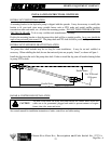
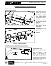
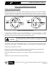
Position the mounting bracket so that the pump drive shaft will be as straight possible. In no case should the
angle of any universal joint exceed 15º. The pump shaft and PTO shaft should be parallel. (Figure 1)
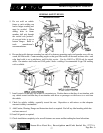
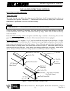
HYDRAULIC PUMP DRIVE SHAFT INSTALLATION
The pump drive shaft included may be too long for some installations. It may be cut and redrilled as
necessary. When redrilling the shaft, be sure that universal joints are properly “timed”, as shown in Figure 1.
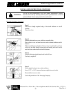
Install the slip joint at the end of the pump drive shaft. Failure to install the slip joint will result in bearing failure
in pump, PTO or both.
Figure 1 - Timing of Universal Joints
RADAR & CONTROLLER INSTALLATION
See control manual for installation instructions of radar, control box and cable routing.
Parallel Shafts
Not To Exceed
15 Degrees
Parallel Forks
All holes in the truck cab walls, floor and firewall for control wires, hoses and
cables are to be grommeted, plugged and sealed to prevent entrance of engine
fumes, dust, dirt, water and noise.
CAUTION