


77
MN002000A © 2004 Navman NZ Ltd. All rights reserved. Proprietary information and specifications subject to change without notice.
as antennas and processors. This equipment
allows users to receive, decode, and process the
information necessary to obtain accurate position,
velocity, and timing measurements. This data
is used by the receiver’s support equipment for
specific application requirements. GPS supports
a wide variety of applications including navigation,
surveying, and time transfer. Receivers may be
used in a stand-alone mode or integrated with
other systems to enhance the overall system
performance.
GPS System operation
How A GPS Receiver Determines Position
A GPS receiver determines its geographic position
by measuring the ranges (the distance between
a satellite with known coordinates in space and
the receiver’s antenna) of several satellites and
computing the geometric intersection of these
ranges.
To determine a range, the receiver measures the
time required for the GPS signal to travel from
the satellite to the receiver antenna. The timing
code generated by each satellite is compared
to an identical code generated by the receiver.
The receiver’s code is shifted until it matches the
satellite’s code. The resulting time shift is multiplied
by the speed of light to arrive at the apparent range
measurement.
Since the resulting range measurement contains
propagation delays due to atmospheric effects,
and satellite and receiver clock errors, it is referred
to as a ‘pseudorange’. Changes in each of these
pseudo-ranges over a short period of time are
also measured and processed by the receiver.
These measurements, referred to as ‘delta-
pseudoranges’, are used to compute velocity.
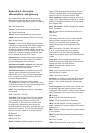
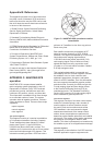
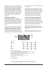
A minimum of four pseudo-range measurements
are required by the receiver to mathematically
determine time and the three components of
position (latitude, longitude, and altitude). The
equations used for these calculations are shown
in Figure C-2. The solution of these equations may
be visualised as the geometric intersection of four
ranges from four known satellite locations.
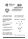
Figure C-3 illustrates ‘triangulation’, one way
to envision the navigation process. For ease of
understanding, it is assumed that the user clock is
synchronous.
After the four range equations are solved, the
receiver has estimates of its position and time.
R
1
U
x
U
y
U
z
C
B
=
CDt
1
(X
1
-
2
+ (Y
1
-
2
+ (Z
1
- )
2
= (R
1
- )
2
R
2
U
x
U
y
U
z
C
B
=
CDt
1
(X
2
-
2
+ (Y
2
-
2
+ (Z
2
- )
2
= (R
2
- )
2
U
x
U
y
U
z
C
B
=
CDt
1
(X
3
-
2
+ (Y
3
-
2
+ (Z
3
- )
2
= (R
3
- )
2
U
x
U
y
U
z
C
B
=
CDt
1
(X
4
-
2
+ (Y
4
-
2
+ (Z
4
- )
2
= (R
4
- )
2
R
3
R
4
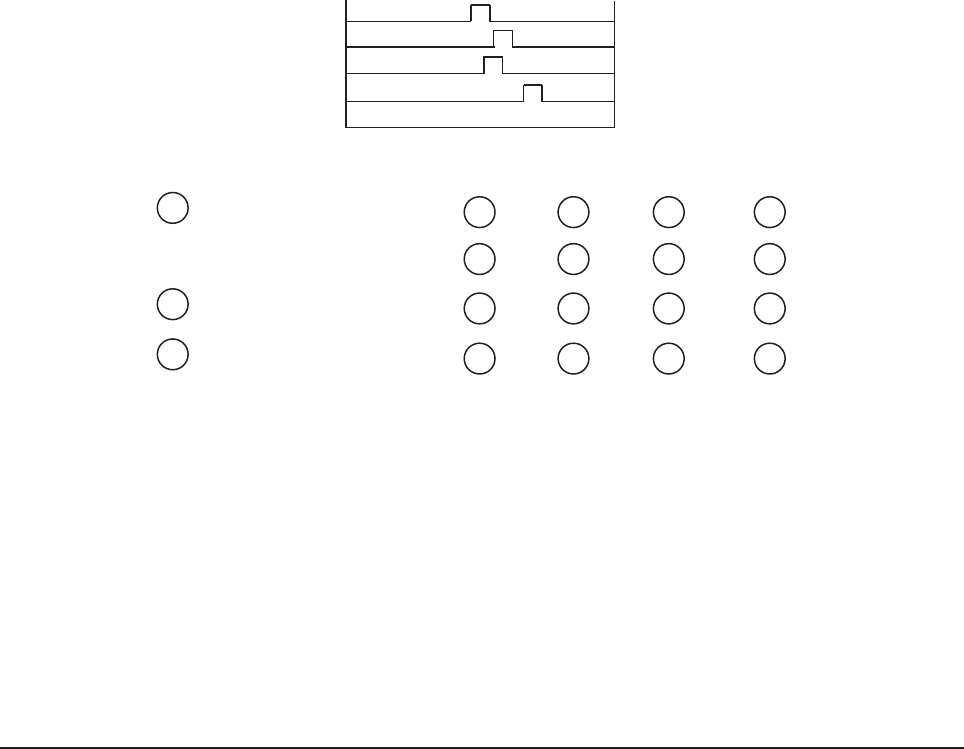
Pseudo ranges Position equations
DT1
DT2
DT3
DT4
R
1
= C x DT
1
R
2
= C x DT
2
R
3
= C x DT
3
R
4
= C x DT
4
(C = speed of light)
Time signals
transmitted
by satellite
R
1
= pseudo range (i = 1,2,3,4)
• Pseudo range includes actual distance between satellite and user plus satellite clock
bias, user clock bias, atmospheric delays, and receiver noise.
• Satellite clock bias and atmospheric delays are compensated for by incorporation of
deterministic corrections prior to inclusion in nav solution.
X
1
, Y
1
, Z
1
= satellite position (i= 1,2,3,4)
• Satellite position broadcast in navigation 50 Hz message.
Receiver solves for:
• U
x
, U
y
, U
z
= user position
• C
B
= user clock bias
Figure C-2 Range processing equations GPS system operation