


45
MN002000A © 2004 Navman NZ Ltd. All rights reserved. Proprietary information and specifications subject to change without notice.
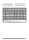
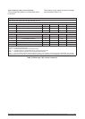
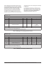
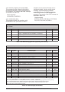
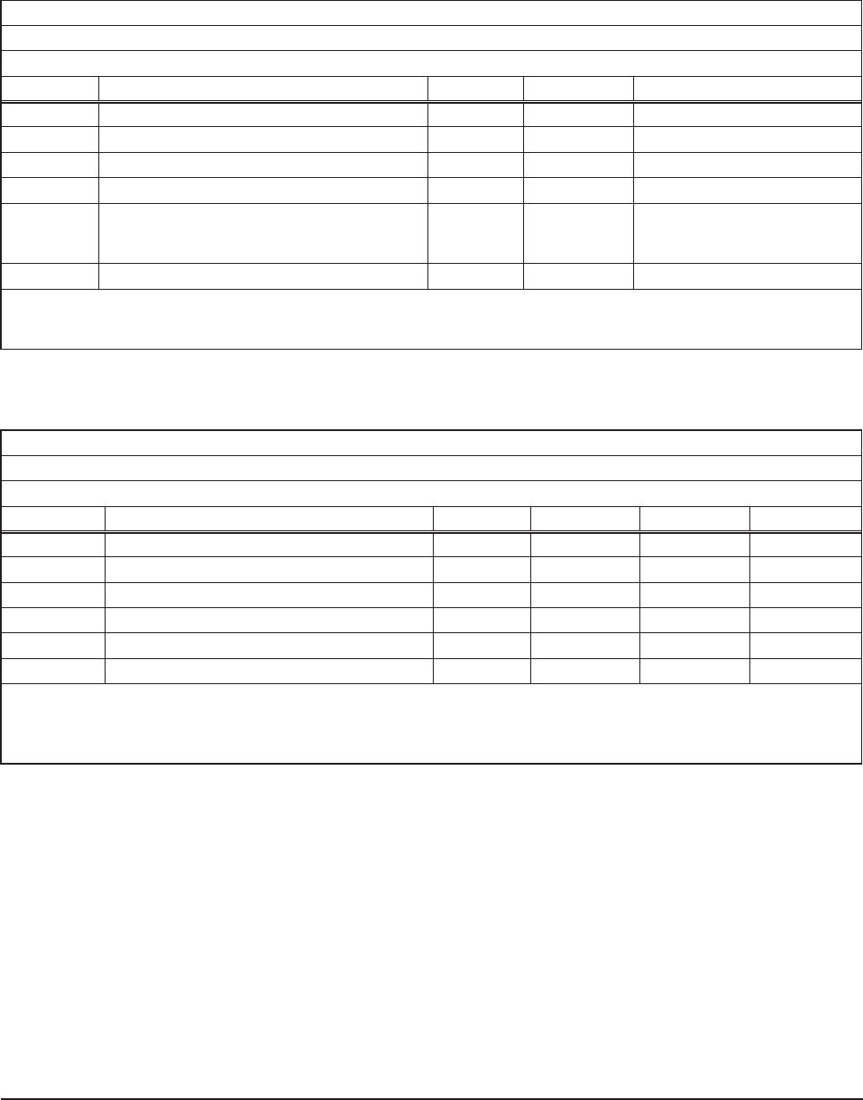
Message ID: 1331
Rate: As required (maximum rate 1 Hz)
Message Length: 9 words
Word No. Name Type Units Range
1-4 Message header
5 Header checksum
6 Sequence number (Note 1) I 0 to 32 767
7 Reserved (must be zeroed out) I
8 Protocol type (Note 2) I
0 = binary
1 = NMEA
2 = RTCM SC-104
9 Data checksum
Note 1: The sequence number is a count that indicates whether the data in a particular binary message has been
updated or changed since the last message input.
Note 2: RTCM SC-104 is not a valid protocol for the host data stream.
Table 3-39 Message 1331 (message protocol control)
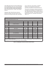
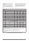
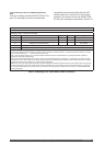
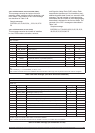
Message ID: 1350
Rate: As required (maximum rate 1 Hz)
Message Length: 10
Word No. Name Type Units Range Resolution
1-4 Message header
5 Header checksum
6 Sequence number (Note 1) I 0 to 32 767
7 Oscillator temperature (Note 2) I
o
C –40 to +85 0.01
8-9 Oscillator frequency error
I ppm 0 to ±51 0.01
10 Data checksum
Note 1: The sequence number is a count that indicates whether the data in a particular binary message has been
updated or changed since the last message input.
Note 2: Externally supplied temperature measurement. An external temperature input causes the internal temperature
sensor to be ignored as a source of temperature data.
Table 3-40 Message 1350 (factory calibration input)
3.5.2.17 Message 1331 (message protocol control)
This message allows the user to set the message
format protocol which will be used to communicate
information to and from the receiver through
the host serial I/O port. Currently, the available
protocols are binary (with fixed-point numbers)
and NMEA-0183. Storage for the protocol type
parameter requires EEPROM. The contents of the
‘message protocol control’ message are described
in Table 3-39.
3.5.2.18 Message 1350 (factory calibration input).
This message is used to inform the system about
the quality of the frequency standard being used.
The contents of the ‘factory calibration input’
message are described in Table 3-40