


6A1 ENGINE (E-W) -
Crankshaft, Cylinder Block, Flywheel and
Drive Plate
11A-15-5
CYLINDER BLOCK
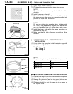
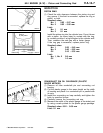
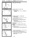
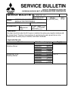
(1) Using a straightedge and feeler gauge, check the block
top surface for warpage. Make sure that the surface is
free from gasket chips an d other foreign matter.
Standard value: 0.05 mm or less
Limit: 0.1 mm
(2) If the distortion is excessive, correct within the allowable
limit or replace.
Grinding limit: 0.2 mm
The total thickness of the stock allowed to be
removed from cylinder block and mating cylinder
head is 0.2 mm at maximum.
Cylinder block height (when new):
6A12 190 mm
6A13 209 mm
(3) Check cylinder walls for scratches and seizure. If defects
are evident, correct (bored to oversize) or replace.
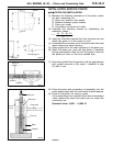
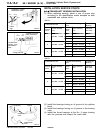
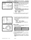
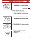
(4) Using cylinder gauge, measure the cylinder bore and
cylindricity. If worn badly, correct cylinder to an oversize
and replace piston and piston rings. Measure at the points
shown in illustration.
Standard value:
Cylinder I.D.:
6A12 78.40 - 78.43 mm
6A13 81.00 - 81.03 mm
Out-of-roundness and taper of cylinder bore:
0.01 mm or less
BORING CYLINDER
(1) Oversize pistons to be used should be determined on
the basis of the largest bore cylinder.
Piston size identification
Size Identification mark
0.50 mm O.S. 0.50
1.00 mm O.S. 1.00
NOTE
Size mark is stamped on piston top.
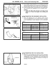
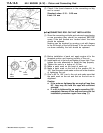
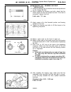
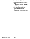
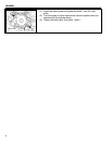
(2) Measure outside diameter of piston to be used. Measure
it in thrust direction as shown.
(3) Based on measured piston O.D. calculate boring finish
dimension.
Boring finish dimension = Piston O.D. + (Clearance
between piston O.D. and cylinder) - 0.02 mm (honing
margin)
PWEE9622
E
Feb. 1997Mitsubishi Motors Corporation
6AE0103
A
B
CDE
F
G
6AE0104
12 mm
6AE0105