


6A1 ENGINE (E-W) -
Piston and Connecting Rod
11A-14-7
INSPECTION
PISTON RING
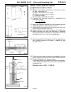
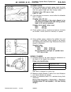
(1) Check the side clearance between the piston ring and
ring groove. If the limit is exceeded, replace the ring or
piston, or both.
Standard value:
No. 1 0.03 - 0.07 mm
No. 2 0.02 - 0.06 mm
Limit:
No. 1 0.1 mm
No. 2 0.1 mm
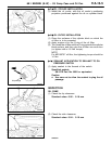
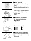
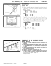
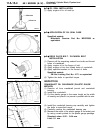
Install the piston ring into the cylinder bore. Force it down
with a piston, its crown being in contact with the ring,
to correctly position it at right angles to th e cylinder wall.
Then, measure the end gap with a feeler gauge.
If the ring gap is excessive, replace piston ring.
Standard value:
No. 1 0.25 - 0.40 mm
No. 2 0.40 - 0.55 mm
Oil 0.10 - 0.35 mm
Limit:
No. 1, No. 2 0.8 mm
Oil 1.0 mm
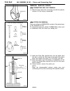
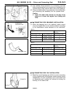
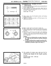
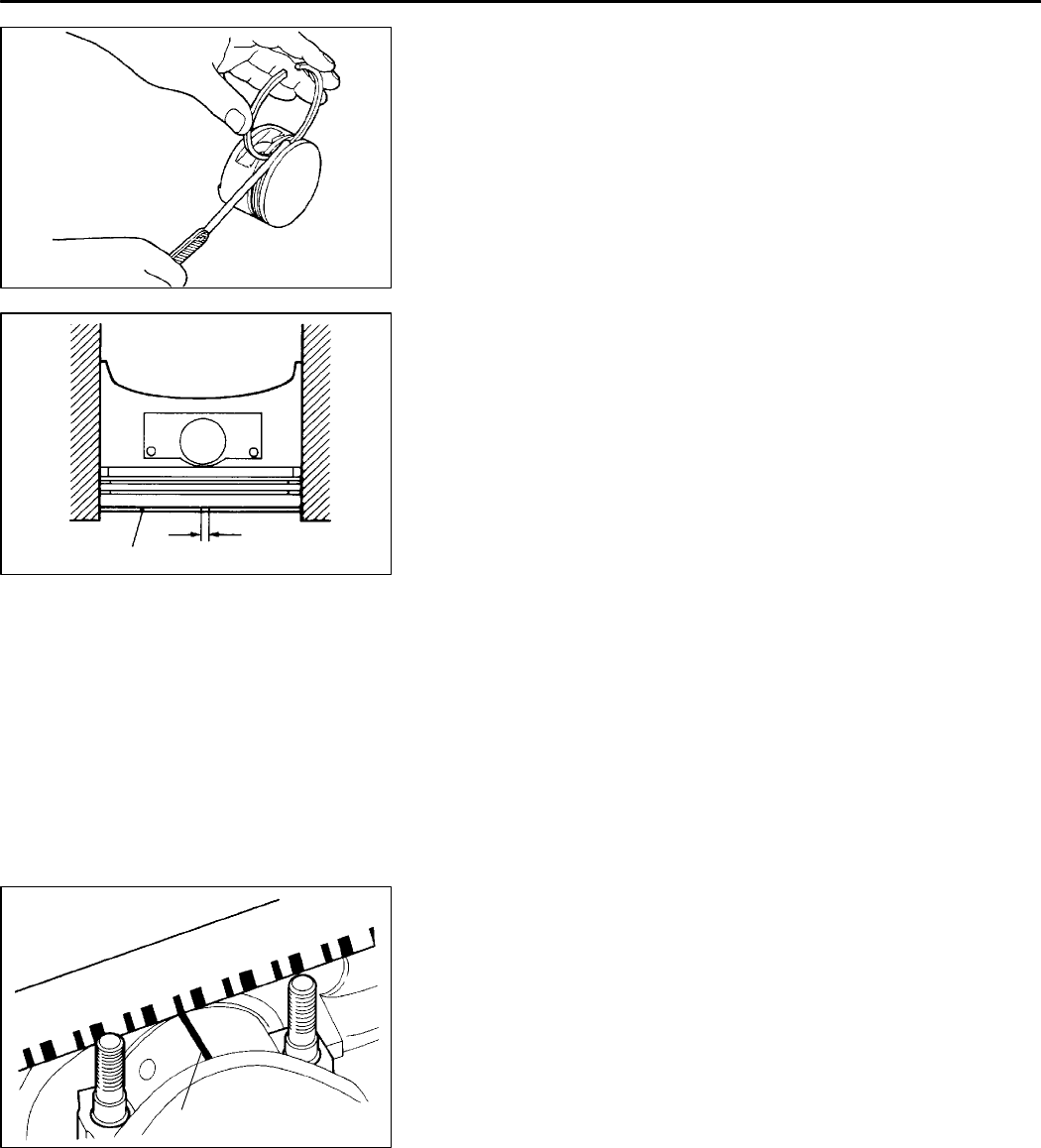
CRANKSHAFT PIN OIL CLEARANCE (PLASTIC
GAUGE METHOD)
(1) Remove oil from crankshaft pin an d connecting rod
bearing.
(2) Cut the plastic gauge to the same length as the width
of bearing and place it on crankshaft pin in parallel with
its axis.
(3) Install the connecting rod cap carefully and tighten the
bolts to specified torque.
(4) Carefully remove the connecting rod cap.
(5) Measure the width of the plastic gauge at its widest part
by using a scale printed on the plastic gauge package.
Standard value: 0.02 - 0.05 mm
Limit: 0.1 mm
PWEE9622
E
Feb. 1997Mitsubishi Motors Corporation
7EN0475
7EN0476
Push in
by the piston
Piston ring
Piston
ring gap
1EN0246
Plastic gauge