


6A1 ENGINE (E-W) -
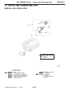
Piston and Connecting Rod
11A-14-6
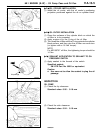
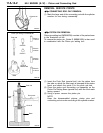
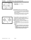
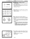
(2) Check if the thrust clearance in the connecting rod big
end is correct.
Standard value: 0.10 - 0.25 mm
Limit: 0.4 mm
"
G
A
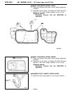
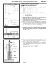
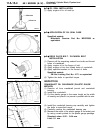
CONNECTING ROD CAP NUT INSTALLATION
(1) Since the connecting rod bolts and nuts are torqued using
a new procedure they should be examined BEFORE
reuse. If the bolt threads are “necked down” the bolts
should be replaced.
Necking can be checked by running a nut with fingers
to the full length of the bolt’s thread. If the nut does not
run down smoothly, the bolt should be replaced.
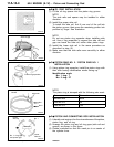
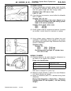
(2) Before installation of each nut, apply engine oil to the
threaded portion and bearing surface of the nut.
(3) Install each nut to the bolt and tighten it finger tight. Then
tighten the nuts alternately to install the cap properly.
(4) Tighten the nuts to a torque of 18 Nm.
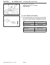
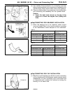
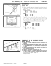
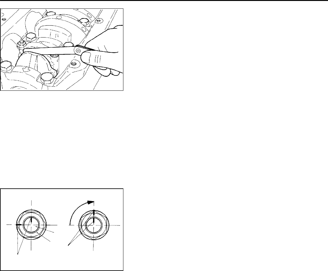
(5) Make a paint mark on the head of each nut.
(6) Make a paint mark on the bolt at the position 90° to
100° from the paint mark made on the nut in the direction
of tightening the nut.
(7) Give a 90° to 100° turn to the nut and make sure that
the paint mark on the nut an d that on the bolt are in
alignment.
Caution
D
If the nuts are tightened by an angle of less than
90
°
, they may not hold the caps with sufficient
strength.
D
If a nut is tightened by an angle exceeding 100
°
,
completely remove all the nuts and carry out the
installation procedure again from step (1).
PWEE9622
E
Feb. 1997Mitsubishi Motors Corporation
9EN0073
6EN0954
90
°
- 100
°
Paint
marks
Nut
Bolt
Paint
marks