


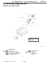
6A1 ENGINE (E-W) -
Piston and Connecting Rod
11A-14-5
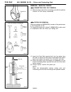
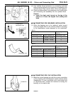
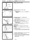
(4) Use suitable thread protectors on connecting rod bolts
before inserting piston and connecting rod assembly into
cylinder block. Care must be taken not to nick crank pin.
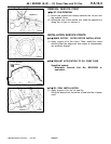
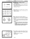
(5) Using a suitable piston ring compressor tool, install piston
and connecting rod assembly into the cylinder block.
Caution
D
Insert the front mark (arrow) on the top of the
piston so it faces the engine front (timing belt
side).
"
E
A
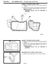
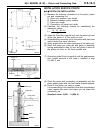
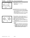
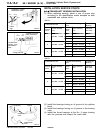
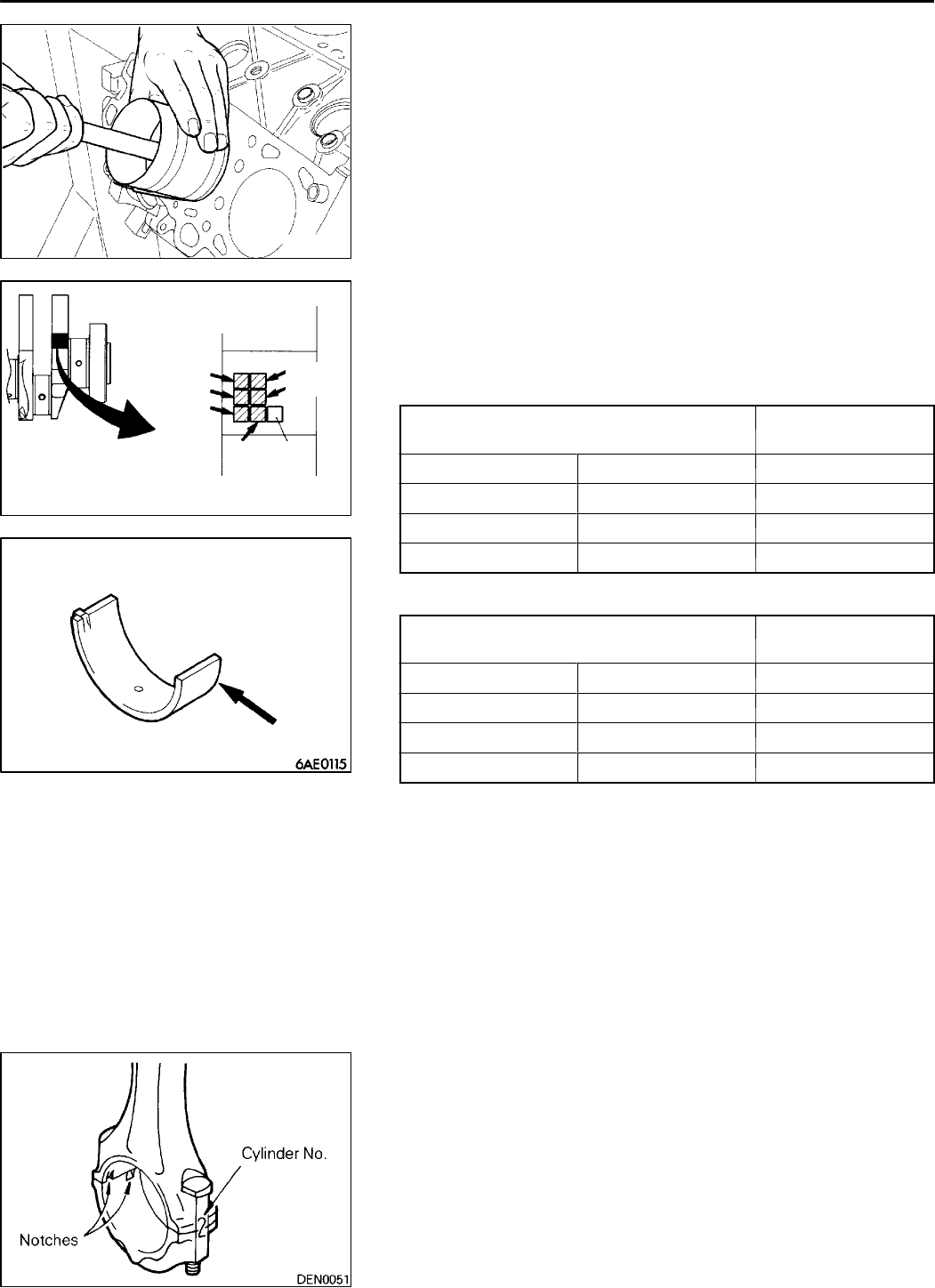
CONNECTING ROD BEARINGS INSTALLATION
(1) When the bearings are to be replaced, select correct
ones and install them in the correct positions according
to the identification marks stamped on th e crankshaft.
<6A12>
Crankshaft pin
Connecting rod
bearing
Identification mark Outer diameter mm Identification mark
I
42.995 - 43.000 1
II
42.985 - 42.995 2
III
42.980 - 42.985 3
<6A13>
Crankshaft pin
Connecting rod
bearing
Identification mark Outer diameter mm Identification mark
I
50.995 - 51.000 1
II
50.985 - 50.995 2
III
50.980 - 50.985 3
"
F
A
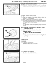
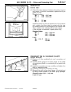
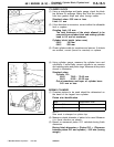
CONNECTING ROD CAP INSTALLATION
(1) Mate the correct bearing cap with t he correct connecting
rod by checking with the alignment marks marked during
disassembly. If a new connecting rod is used which has
no alignment mark, position the notches for locking the
bearing on t he same side.
PWEE9622
E
Feb. 1997Mitsubishi Motors Corporation
6AE0097
6AE0341
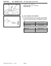
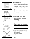
Crankshaft pin
identification mark
Check
digit
No.1
No.3
No.5
No.2
No.4
No.6
Identification mark