


6A1 ENGINE (E-W) -
Crankshaft, Cylinder Block, Flywheel and
Drive Plate
11A-15-1
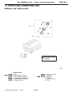
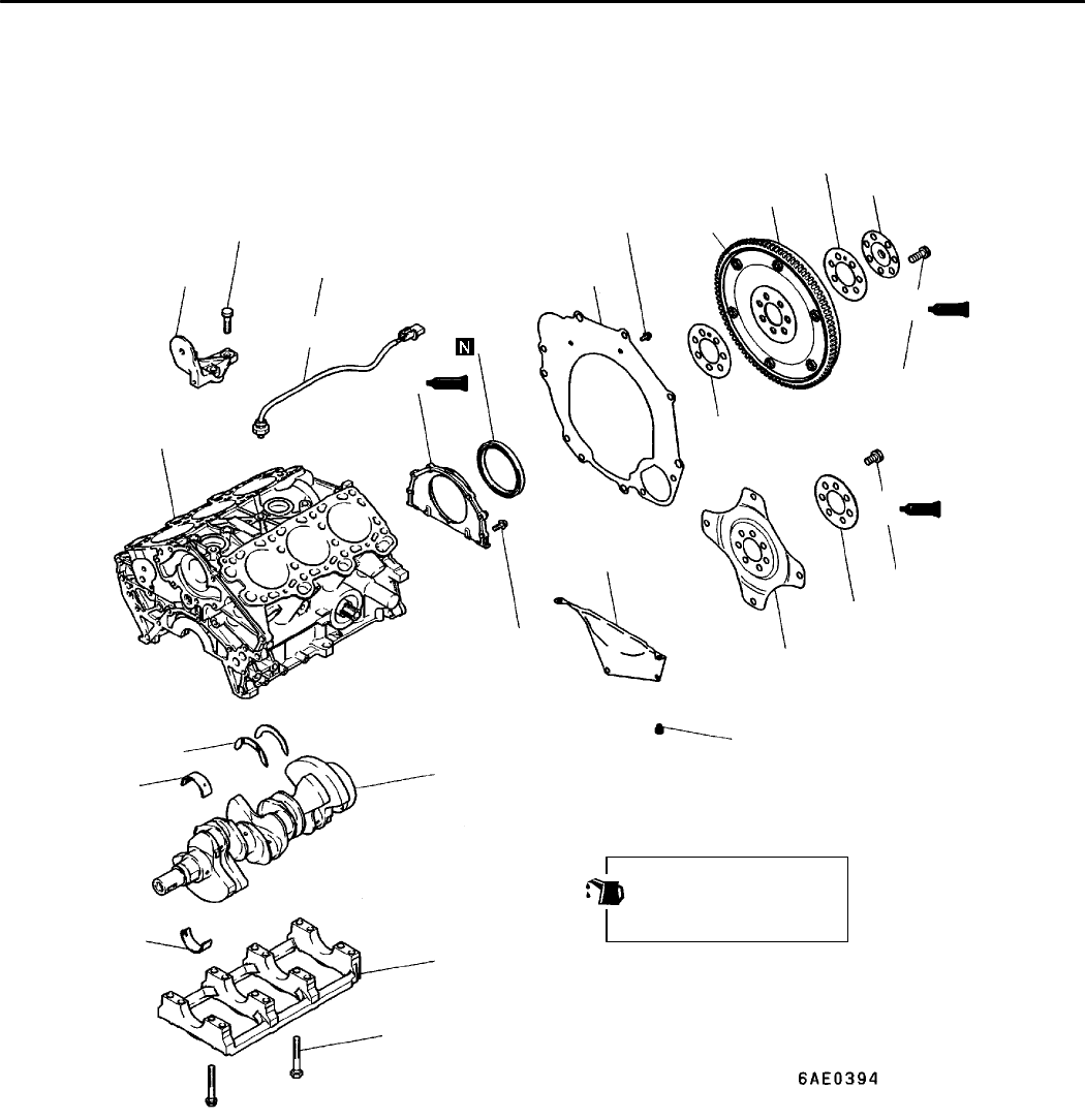
15. CRANKSHAFT, CYLINDER BLOCK, FLYWHEEL AND DRIVE
PLATE
REMOVAL AND INSTALLATION
1
2
3
4
5
6
7
8
9
10
11
12
13
14
15
16
17
23 Nm
35 Nm
20
19
18
21
9Nm
11 Nm
98 Nm
98 Nm
A
11 Nm
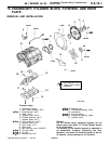
Apply engine oil t o all
moving parts before
installation.
Removal steps
1. Detonation sensor
2. Idler pulley bracket <M/T>
"
E
A 3. Flywheel bolt <M/T>
4. Plate <M/T>
5. Adapter plate <M/T>
6. Flexible flywheel <M/T>
7. Adapter plate <M/T>
"
E
A 8. Drive plate bolt <A/T>
9. Adapter plate <A/T>
10. Drive plate <A/T>
11. Rear plate
12. Bell housing cover <MIVEC>
"
D
A 13. Oil seal case
"
C
A 14. Oil seal
"
B
A 15. Bearing cap bolt
"
B
A 16. Bearing cap
"
A
A 17. Crankshaft bearing, lower
18. Crankshaft
"
A
A 19. Thrust bearing
"
A
A 20. Crankshaft bearing, upper
21. Cylinder block
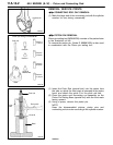
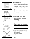
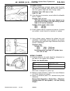
Caution
On the flexible wheel equipped engines, do not
remove any of the bolts “A” of the flywheel shown
in the illustration.
The balance of the flexible flywheel is adjusted in
an assembled condition. Removing the bolt,
therefore, can cause the flexible flywheel to be out
of balance, giving damage to the flywheel.
PWEE9622
E
Feb. 1997Mitsubishi Motors Corporation