BASIC BRAKE SYSTEM -
On-vehicle Service
35A-9
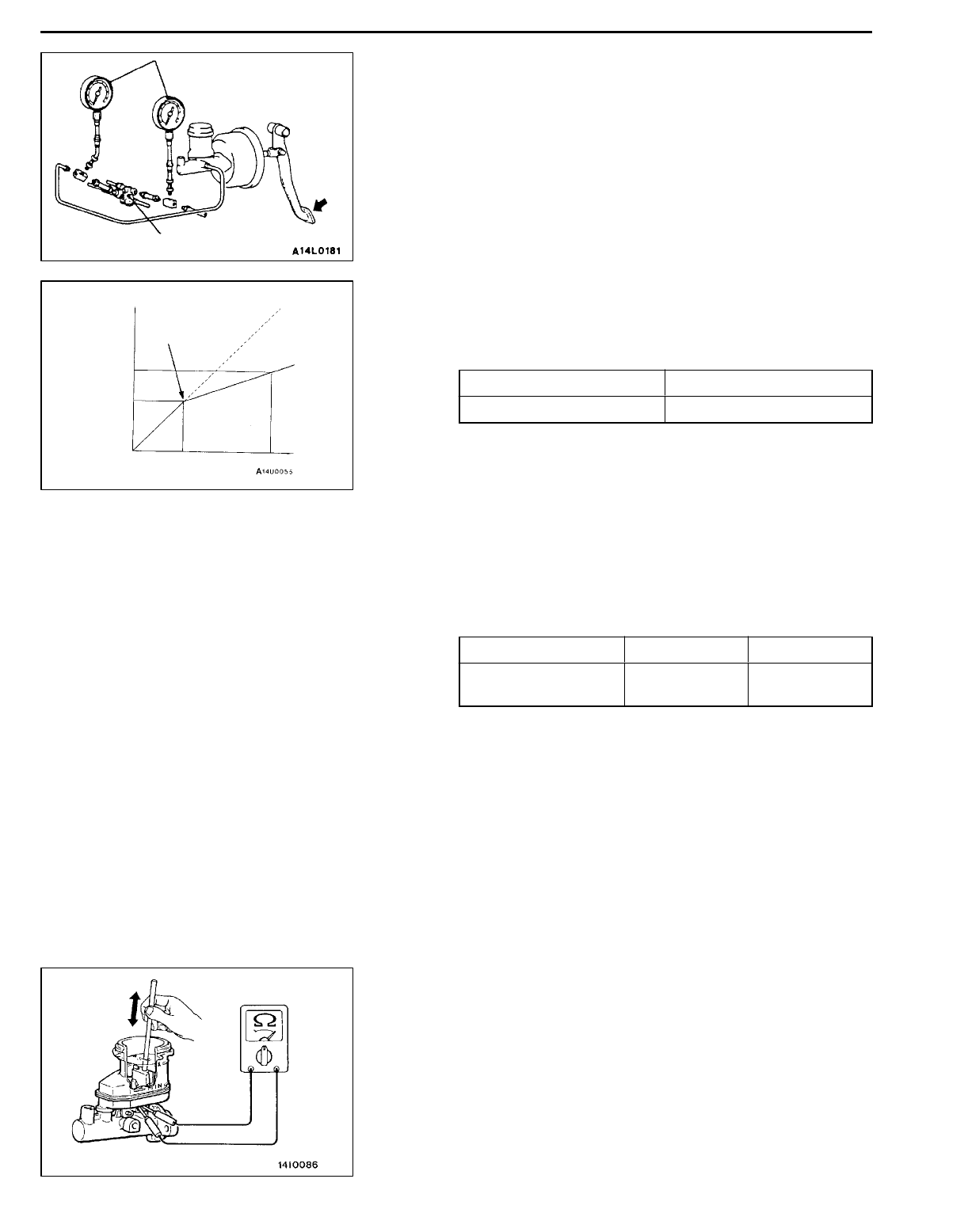
PROPORTIONING VALVE FUNCTION TEST
35100110172
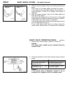
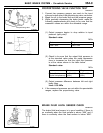
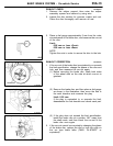
1. Connect two pressure gauges, one each to the input
side and output side of the proportioning valve, as shown.
2. Bleed the air in the brake line and the pressure gauge.
3. While gradually depressing the brake pedal, make the
following measurements and check to be sure that the
measured values are within the allowable range.
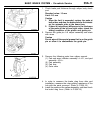
(1) Output pressure begins to drop relative to input
pressure (split point).
Standard value:
MPa
Sedan Wagon
2.94
±
0.25 3.43
±
0.25
(2) Check to be sure that the output fluid pressure is
at the standard value when the pedal depression
force is increased so that the input fluid pressure
is at the values shown in the table below.
Standard value:
MPa
Sedan W agon
Output fluid pressure
(Input fluid pressure)
4.66
±
0.39
(9.81)
5.80
±
0.39
(9.81)
(3) Output pressure difference between left and right
brake lines.
Limit: 0.39 MPa
4. If the measured pressures are not within the permissible
ranges, replace the proportioning valve.
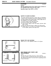
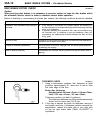
BRAKE FLUID LEVEL SENSOR CHECK
35100910123
The brake fluid level sensor is in good condition if there is
no continuity when the float surface is above “MIN” and if
there is continuity when the float surface is below “MIN”.
Pressure gauge
Proportioning valve
Split point
Output
pressure
Input pressure


