


ABS <2WD> -
Hydraulic Unit
35B-27
REMOVAL SERVICE POINT
A
A
"
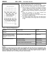
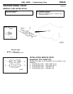
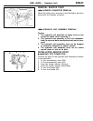
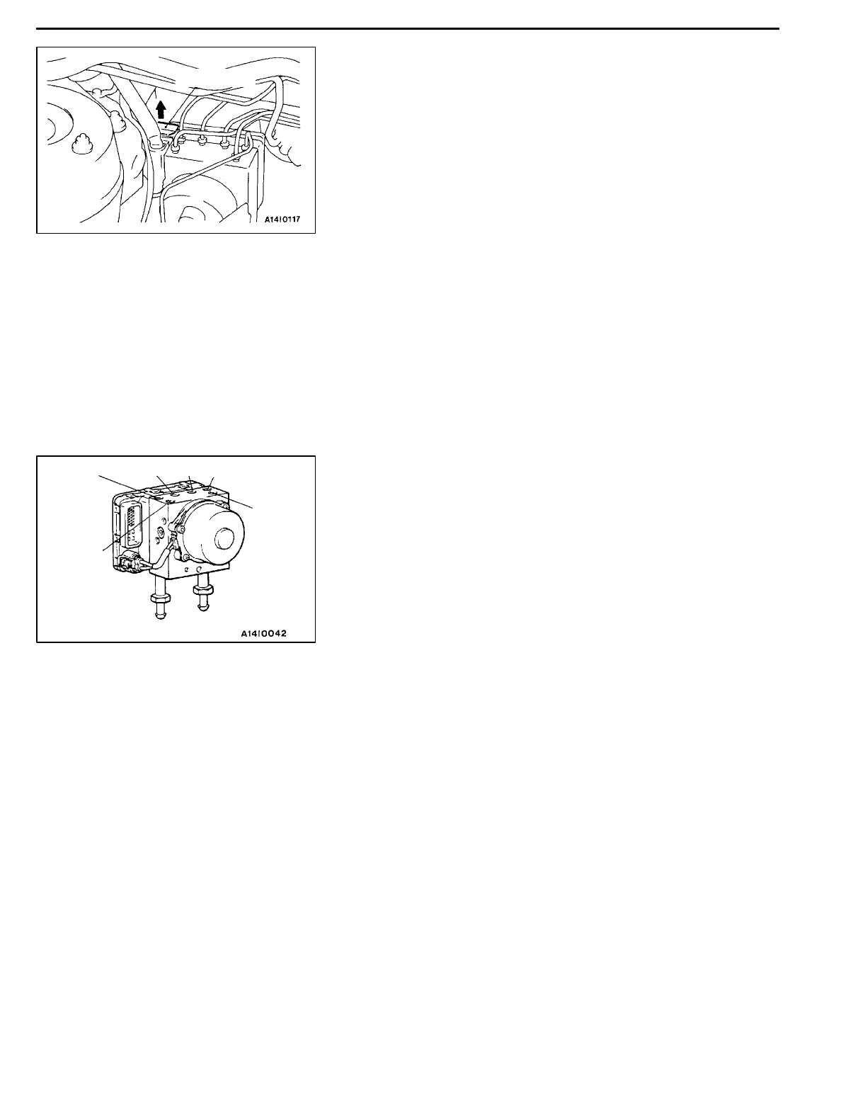
HARNESS CONNECTOR REMOVAL
Raise the locking lever as shown in the illustration, and then
disconnect the harness connector.
A
B
"
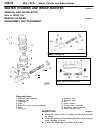
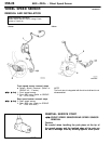
HYDRAULIC UNIT ASSEMBLY REMOVAL
Caution
1. The hydraulic unit assembly is heavy, and so care
should be taken when removing it.
2. The hydraulic unit assembly is not to be disassem-
bled; its nuts and bolts should absolutely not be loos-
ened.
3. The hydraulic unit assembly must not be dropped
or otherwise subjected to impact shocks.
4. The hydraulic unit assembly must not be turned
upside down or laid on its side.
INSTALLATION SERVICE POINT
"
A
A
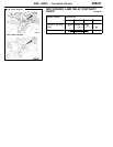
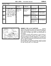
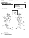
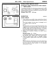
BRAKE PIPE CONNECTION
Connect the pipes to the hydraulic unit assembly as shown
in the illustration.
1. To the proportioning valve (RH)
2. To the proportioning valve (LH)
3. From the master cylinder (Primary)
4. From the master cylinder (Secondary)
5. To the front brake (RH)
6. To the front brake (LH)
Locking lever
3
4
6
1
5
2