BASIC BRAKE SYSTEM -
On-vehicle Service
35A-7
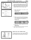
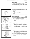
Standard value: 3–8 mm
If the free play exceeds the standard value, it is probably
due to excessive play between the retaining ring bolt and
brake pedal arm.
Check for excessive clearance and replace faulty parts as
required.
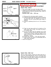
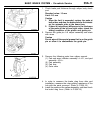
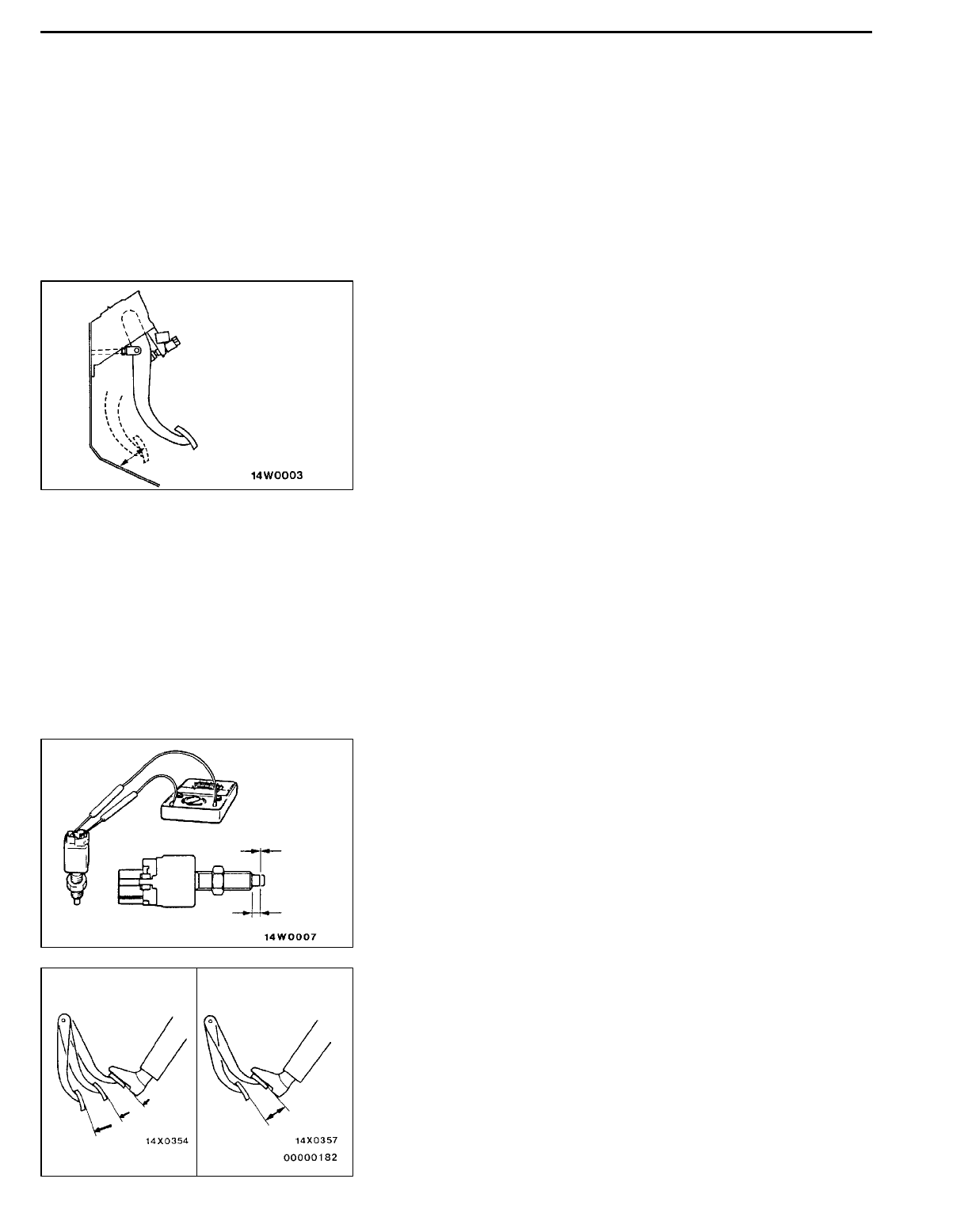
CLEARANCE BETWEEN BRAKE PEDAL AND FLOOR
BOARD
1. Turn back the carpet etc. under the brake pedal.
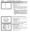
2. Start the engine, depress the brake pedal with
approximately 490 N of force, a n d measure the clearance
between the brake pedal and the floorboard.
Standard value: 90 mm or more
3. If the clearance is outside the standard value, check for
air trapped in the brake line, clearance between the lining
and the drum an d dragging in the parking brake.
Adjust and replace defective parts as required.
4. Return the carpet etc.
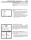
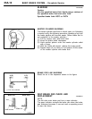
STOP LAMP SWITCH CHECK
35100890120
Connect a circuit tester to the stop lamp switch, and check
whether or not there is continuity when the plunger of the
stop lamp switch is pushed in and when it is released. The
stop lamp switch is in good condition if there is no continuity
when the plunger is pushed in to a depth of within 4 mm
from the outer case edge surface, and if there is continuity
when it is released.
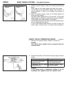
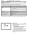
BRAKE BOOSTER OPERATING TEST
35100100117
For simple checking of t h e brake booster operation, carry
out the following tests:
1. Run the engine for one or two minutes, and then stop
it.
If the pedal depresses fully the first time but gradually
becomes higher when depressed succeeding times, the
booster is operating properly, if the pedal height remains
unchanged, the booster is defective.
No continuity
Continuity
4mm
Good No good


