7
MITSUBISHI ELECTRIC
FR-F 740 EC/E1
Flying start
Gentle restart of a rotating motor (e.g. fan
rotated by a draft), also in the opposite di
-
rection.
PTC temperature sensor input
The motor’s internal PTC temperature sen
-
sor can be connected to the inverter di
-
rectly. In combination with the electronic
temperature monitoring system this provi
-
des effective protection for the motor.
Active current limiting
Tried and tested capabilities like the active
current limiting feature have been retai
-
ned. The characteristics of the current limi
-
ter have now been further improved to
prevent unwanted triggering in response
to overcurrents. Transient overcurrents, for
example those generated when a motor
coasting in reverse is restarted or when an
input contactor is closed, will no longer
cause unwanted triggering of the current
limiter.
Magnetic flux vector control
The integrated motor flux vector control
system makes it possible to achieve high
torques, even at low motor speeds.
Optimum excitation control
You can also select the optimum excitation
control mode, which achieves yet more
power savings compared to conventional
inverters designed for pump and fan appli
-
cations.
The graph below demonstrates the kind of
improvements that are possible with this
control mode:
Regeneration avoidance function
This function can prevent the inverter from
being shut down by regenerative overvol
-
tages when strong regenerative loads cau
-
se power to be released into the frequency
inverter (for example when braking the
motor or with loads that actively drive the
motor).
The inverter can automatically increase the
output frequency or disable the braking
ramp when a programmed threshold value
is reached. The response sensitivity, dyna
-
mics and working range are all adjustable.
For example, this function can prevent a
shutdownwithanovervoltageerrorwhen
the speed of a fan controlled by the inver
-
ter is increased by the draft from another
fan operating in the same ventilation duct.
The function then temporarily increases
the output frequency above the setpoint
value.
This function can also be used to brake lo
-
ads with the DC bus voltage, without using
braking modules.
Switching to direct mains operation
You can switch the motor to direct mains
operation by programming the contactor
relays accordingly and applying a control
signal to terminals L11 and L21 of the
inverter.
100
90
80
70
60
50
40
30
20
10
0
5% 10% 25% 50% 75% 100% 120%
Torqueload (percentage of rated torque load)
Optimum excitation control mode
Motor efficiency (percent)
Standard energy saving inverter
No excitation control
SYSTEM DESCRIPTION
f2
f3
f1
f1
f0
(Hz)
t1
(Pr.596) t2 (Pr.597)
t(s)
Pr.7
Pr.7
Pr.8
ON
ON
Output frequency
Start/stop
signal
X37 signal
Time (s)
Traverse function
Innovative Features and Functions
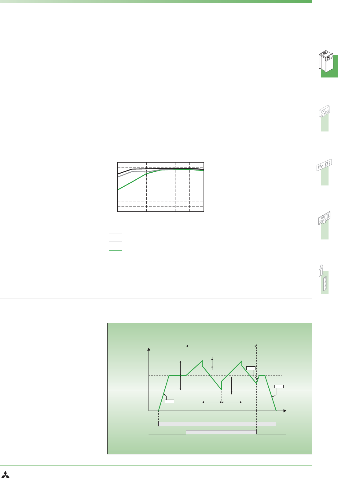
Traverse function
The traverse function of the FR-F740 is de
-
signed specifically for use in yarn-winding
applications in the textile industry.
This function performs a cyclical variation
of the output frequency as shown in the
graph on the right. The width of the fluc
-
tuation around the frequency setpoint va
-
lue and the ramp times are configurable
via setup parameters.
This function prevents the formation of the
unwanted “bands” in the wound yarn.


