


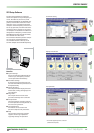

17
MITSUBISHI ELECTRIC
FR-F 740 EC/E1
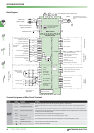
SYSTEM DESCRIPTION
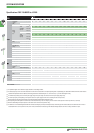
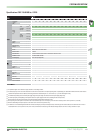
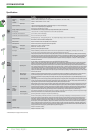
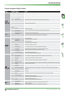
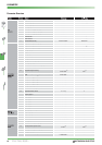
Terminal Assignment of Signal Terminals
STF Forward rotation start
The motor rotates forward,if a signal is applied to terminal STF.
STR Reverse rotation start
The motor rotates reverse,if a signal is applied to terminal STR.
STOP Startself-retaining selection
The start signals are self-retaining,if a signal is applied to terminal STOP.
RH, RM,RL Multi-speed selection
Preset of 15 different output frequencies
JOG Jog mode selection
The JOG mode is selected,if a signal is applied to terminal JOG (factory setting).The inverters FR-A 540L-G 375 k and 450 k are not
equipped with a JOG terminal.The start signals STF and STR determine the rotation direction.
RT Second parameter settings
A second set of parameter settings is selected,if a signal is applied to terminal RT.
MRS Outputstop
The inverter lock stops the output frequency without regard to the delay time.You can select a make or break signal for the controller
inhibit function by changing parameter 17.
RES RESET input
An activated protective circuit is reset,if a signal is applied to the terminal RES (t > 0,1 s).
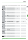
AU
Current input selection
The 0/4–20mA signal on terminal 4 is enabled by a signal on the AU terminal.
PTC input
If you connect a PTC temperature sensor you must assign the PTC signal to the AU terminal and set the slide switch on the control cir
-
cuit board to the PTC position.
CS
Automatic restart after instanta
-
neous power failure
The inverter restarts automatically after a power failure,if a signal is applied to the terminal CS.
SD
Reference potential (0V) for the
PC terminal (24V)
When “sink”control logic is selected by setting the control signal jumper a specific control function is triggered when the correspond
-
ing control terminal is connected to the SD terminal.
When “source”control logic is selected and you are using external 24V power you must connect the 0V of the external power supply to
terminal SD.The SD terminal is isolated from the digital electronics with optocouplers.
PC 24 V DC output
Internal power supply 24 V DC/0,1 A output
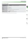
10 E
Voltage output for
potentiometer
Output voltage 10 V DC.
Max.output current 10 mA.
Recommended potentiometer:1 kΩ,2 W linear
10
Output voltage 5 V DC.
Max.output current 10 mA.
Recommended potentiometer:1 kΩ,2 W linear
2
Input for frequency setting
value signal
The setting value 0–10 V or 0/4–20 mA is applied to this terminal. You can switch between voltage and current setpoint values with
parameter 73.The input resistance is 10 kΩ.
5
Reference point for frequency
setting value signal
Terminal 5 is the reference point for all analog setting values and for the analog output signal AM and CA.The terminal is not isolated
from the reference potential of the control circuit and must not be earthed.
1
Auxiliary input for frequency set-
ting value signal
0–±5 (10) V DC
An additional voltage setting value signal of 0–±5 (10) V DC can be applied to terminal 1.
The voltage range is preset to 0–±10 V DC.The input resistance is 10 kΩ.
4 Input for setting value signal
The setting value 0/4–20 mA or 0–10 V is applied to this terminal.You can switch between voltage and current setpoint values with
parameter 73.The input resistance is 250 Ω.
The current setting value is enabled via terminal function AU.
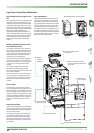
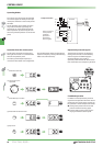
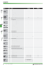
A1, B1, C1
Potential free
Relay output 1 (Alarm)
The alarm is output via relay contacts.The block diagram shows the normal operation and voltage free status.If the protective
function is activated,the relay picks up.The maximum contact load is 200 V AC / 0.3 A or 30 V DC / 0.3 A.
A2, B2, C2
Potential free
Relay output 2
Any of the available 42 output signals can be used as the output driver.
The maximum contact load is 230 V AC / 0.3 A oder 30 V DC / 0.3 A.
RUN
Signal output for motor
operation
The output is switched low, if the inverter output frequency is equal to or higher than the starting frequency.
The output is switched high,if no frequency is output or the DC brake is in operation.
SU
Signal output for frequency set
-
ting value/current value
comparison
The SU output supports a monitoring of frequency setting value and frequency current value.The output is switched low,once the fre
-
quency current value (output frequency of the inverter) approaches the frequency setting value (determined by the setting value sig
-
nal) within a preset range of tolerance.
IPF
Signal output for instantaneous
power failure
The output is switched low for a temporary power failure within a range of 15 ms≤t
IPF
≤100 ms or for under voltage.
OL Signal output for overload alarm
The OL is switched low,if the output current of the inverter exceeds the current limit preset in parameter 22 and the stall prevention is
activated.If the output current of the inverter falls below the current limit preset in parameter 22,the signal at the OL output is
switched high.
FU
Signal output for monitoring
output frequency
The output is switched low once the output frequency exceeds a value preset in parameter 42 (or 43).Otherwise the FU output is
switched high.
SE
Reference potential for signal
outputs
The potential that is switched via open collector outputs RUN,SU,OL,IPF and FU is connected to this terminal.
CA Current output 0–20 mA
One of 18 monitoring functions can be selected,e.g.external frequency output. CA and AM output can be used simultaneously.
The functions are determined by parameters.
An amperemeter can be connected (measuring range:0–20 mA).
AM
Analog output 0–10 V
(1 mA)
One of 18 monitoring functions can be selected,e.g.external frequency output.CA and AM output can be used simultaneously.
The functions are determined by parameters.
A DC voltmeter can be connected.The max.output voltage is 10 V.
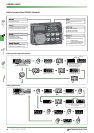
—
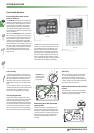
Connection of control panel
(via RS485 terminal)
Communications via RS485
I/O standard:RS485,Multi-Drop operation,4,800 – 38,400 Baud (overall length:500 m)
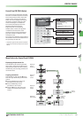
—
RS484 terminal
(via RS485 terminal)
Communications via RS485
I/O standard:RS485,Multi-Drop operation,300 – 38,400 Baud (overall length:500 m)