


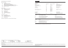

The following abbreviations are used to represent values for Control Module Pin-Out data
I Input PG Power Ground C CAN Network D Serial and Encoded Data
O Output SS Sensor / Signal Supply V S SCP Network V Voltage (DC)
B+ Battery Voltage SG Sensor / Signal Ground D2 D2B Network PWM Pulse Width Modulated
CAUTION: The information on this data page is furnished to aid the user in understanding circuit operation. THIS INFORMATION SHOULD BE USED FOR
REFERENCE ONLY.
NOTE: The values listed are approximately those that can be expected at the control module connector pins with all circuit connections made and all components
connected and fitted.
Refer to the front of this book for detailed information and illustrations regarding the location and identification of harnesses, relays, fuses, grounds, control
modules and control module pins.
DATE OF ISSUE: June 2002
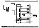
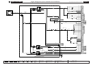
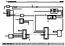
Fig. 01.7
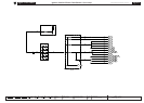
COMPONENTS
Component Connector(s) Connector Description Location
EMS CONTROL RELAY — — FRONT POWER DISTRIBUTION FUSE BOX – R5
ENGINE CONTROL MODULE PI1 134-WAY / BLACK FRONT BULKHEAD, PASSENGER SIDE
FRONT POWER DISTRIBUTION FUSE BOX — — ENGINE COMPARTMENT, RH SIDE
HO2S RELAY —— FRONT POWER DISTRIBUTION FUSE BOX – R2
IGNITION COIL RELAY — — FRONT POWER DISTRIBUTION FUSE BOX – R3
HARNESS IN-LINE CONNECTORS
Connector Connector Description / Location Location
CP1 10-WAY / BLACK / INTERCOOLER PUMP LINK LEAD ENGINE COMPARTMENT, RH FRONT, ADJACENT TO RADIATOR
FH1 20-WAY / BLACK / CABIN HARNESS TO FRONT HARNESS RH ‘A’ POST, LOWER
IL10 12-WAY / BLACK / ENGINE HARNESS TO FUEL INJECTOR LINK REAR OF ENGINE
IS5 6-WAY / BLACK / ENGINE HARNESS TO FUEL INJECTOR LINK ENGINE, LH REAR
IS6 6-WAY / BLACK / ENGINE HARNESS TO FUEL INJECTOR LINK ENGINE, RH REAR
PI41 42-WAY / BLACK / ENGINE HARNESS TO VEHICLE HARNESSES ENGINE COMPARTMENT, BULKHEAD, PASSENGER SIDE
GROUNDS
Ground Location
FH42 ENGINE COMPARTMENT, BEHIND RH HEADLAMP
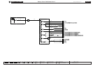
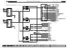
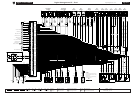
FOR CONTROL MODULE PIN-OUT INFORMATION, UNFOLD PAGE TO LEFT.
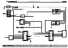
CONTROL MODULE PIN-OUT INFORMATION
Engine Control Module
Pin Description and Characteristic
OPI1-40 EMS CONTROL RELAY DRIVE: TO ACTIVATE, ECM SWITCHES CIRCUIT TO GROUND