


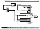
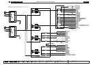

Refer to the front of this book for detailed information and illustrations regarding the location and identification of harnesses, relays, fuses, grounds, control
modules and control module pins.
DATE OF ISSUE: June 2002
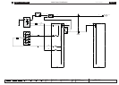
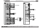
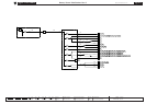
Fig. 01.3
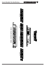
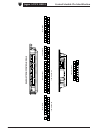
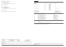
COMPONENTS
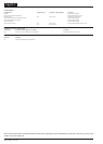
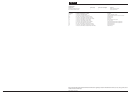
Component Connector(s) Connector Description Location
PRIMARY JUNCTION FUSE BOX CA2 26-WAY / BLACK RH ‘A’ POST
CA56 8-WAY / BLACK
FC37 26-WAY / BLACK
FH7 6-WAY / BLACK
FH53 10-WAY / BLACK
REAR POWER DISTRIBUTION FUSE BOX — — LUGGAGE COMPARTMENT
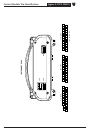
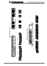
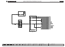
HARNESS IN-LINE CONNECTORS
Connector Connector Description / Location Location
FH1 20-WAY / BLACK / CABIN HARNESS TO FRONT HARNESS RH ‘A’ POST, LOWER
SL3 10-WAY / GREY / FASCIA HARNESS TO SOLAR SENSOR LINK BEHIND INSTRUMENT PANEL, RH SIDE