Jaguar S
-
TYPE 2002.5
12
DATE OF ISSUE: June 2002
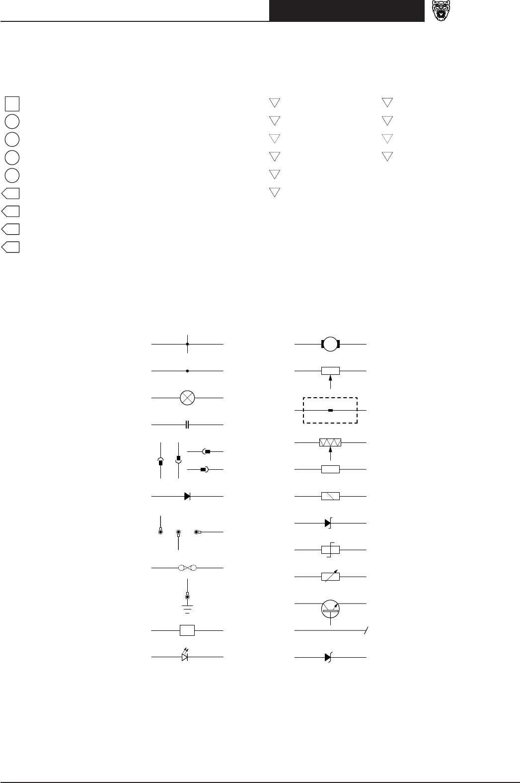
Symbols and Codes
NOTE: In the examples on this page, an ‘X’ is used where a number would appear on an actual Figure.
Reference Symbols
Battery power supply
Ignition switched auxiliary power supply (key I, II)
Ignition switched power supply (key II, III)
Switched System Power Supply power supply
Engine Management System power supply
Figure number reference
Controller Area Network
Standard Corporate Protocol network
D2B network
Wiring Symbols
Simplified splice
Bulb
Capacitor
Connector
Diode
Eyelet and stud
Fuse
Ground
Hall effect sensor
Motor
Potentiometer
Power distribution box terminal
Pressure transducer
Resistor
Solenoid
Suppression diode
Suppression resistor
Thermistor
Transistor
Wire continued
Zener diode
X
XX.X
SCP
CAN
D2B
X
I
X
II
E
X
S
X
H
Light emitting diode (LED)
Splice
Control Module Pin Symbols
Input CAN network
Output SCP network
Battery voltage D2B network
Power ground Serial and encoded data
Sensor/signal supply V *
Sensor/signal ground **
* May also indicate Reference Voltage.
** May also indicate Reference Ground or Logic Ground.
Refer to Control Module Pin-Out Information.
I
O
C
S
+
–
D
D
2
B
+
P


