


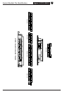
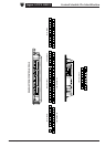
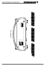
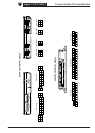


Refer to the front of this book for detailed information and illustrations regarding the location and identification of harnesses, relays, fuses, grounds, control
modules and control module pins.
DATE OF ISSUE: June 2002
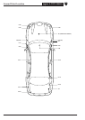
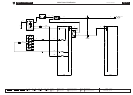
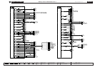
Fig. 01.1
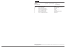
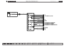
COMPONENTS
Component Connector(s) Connector Description Location
BATTERY —— LUGGAGE COMPARTMENT
FRONT POWER DISTRIBUTION FUSE BOX — — ENGINE COMPARTMENT, RH SIDE
IGNITION SWITCH FC18 7-WAY / BLACK STEERING COLUMN COWLING
REAR POWER DISTRIBUTION FUSE BOX MEGAFUSE — — LUGGAGE COMPARTMENT
REAR POWER DISTRIBUTION FUSE BOX — — LUGGAGE COMPARTMENT
STARTER MEGAFUSE — — LUGGAGE COMPARTMENT
TRANSIT ISOLATION RELAY CA16 2-WAY / WHITE LUGGAGE COMPARTMENT, BATTERY + POST
JB2 NOT AVAILABLE
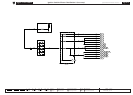
HARNESS IN-LINE CONNECTORS
Connector Connector Description / Location Location
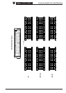
FC39 10-WAY / GREY / CABIN HARNESS TO FASCIA HARNESS BEHIND INSTRUMENT PANEL, RH SIDE
GROUNDS
Ground Location
JB1 LUGGAGE COMPARTMENT, BATTERY GROUND