


1.0 DISASSEMBLY
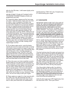
1.1 With the engine running, raise the hood and
locate the main under hood fuse box by the fend-
er well near the firewall on the passenger side of
the engine compartment. Lift the main fuse box
cover and locate the relay labeled “FUEL INJ”.
While the engine is running, remove the “FUEL
INJ” relay. The engine will stop running. Turn
your ignition key off. Store the “FUEL INJ” relay
in a safe place until you are finished with the
installation. Release the pressure in your fuel
tank by removing your gas cap momentarily and
then re-installing.
1.2 Release the airflow meter harness 7-pin con-
nector by lifting the small wire clip that runs
around the rectangular base of the connector.
Remove the stock air flow meter, air filter box and
intake snorkel. Remove the air flow meter from
the air box. Store the air box, filter, and snorkel
away. Move the air flow meter to a safe place on
a worktable.
1.3 Remove the molded rubber elbow and hard
plastic tube that lead from the throttle body to the
airflow meter. If you have cruise control, you will
also have to remove the vacuum line from the
intake manifold nipple and from the points where
it attaches to the hard plastic intake tube.
Remove the cruise control vacuum line from the
cruise actuator as well and save it for use in step
#4.4 later.
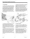
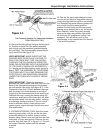
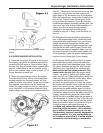
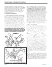
1.4 Remove the chrome crankcase vent pipe that
is attached to the front of the cam cover and the
rubber hose that leads into the cam cover
(Figure 1.4). These can be stored away.
However, find the small restrictor inside the rub-
ber hose that ran from the cam cover to the
chrome tubing. It can be felt as a lump in the
straight section of the hose near the chrome tube
end. Persuade it out by gently clamping the hose
with a pair of pliers just behind the “lump”. Save
this restrictor for step #7.8. Re-install the chrome
bolts that held the tubing in place. Store the
chrome tube and Mazda hoses away.
2.0 THROTTLE BODY
2.1 Remove the throttle body (Figure 1.4) by
releasing the two electrical connectors (one has
a spring wire, one has a plastic lever clip), the
two small coolant hoses on either side of the
lower Idle Control System (ICS) valve, and the
four bolts.
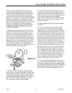
TIP: THE SPRING HOSE CLAMPS FROM
MAZDA ARE BEST REMOVED BY
APPROACHING FROM THE SIDE WITH NEE-
DLE NOSE PLIERS. GRASP ALL THREE
TANGS AT ONCE AND COMPRESS THEM
TOGETHER. THIS IS EASIER TO DO WITH
THE THROTTLE BODY ALREADY LOOSE
FROM THE INTAKE MANIFOLD.
999-156 -2- Revised 1/07
Supercharger Installation Instructions
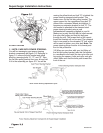
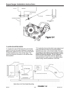
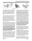
2. Stock Air Filter Box
3. Air Flow
4. Stock Plastic / Rubber Cross Over
5. ICS Valve (Idle Air Control)
6. Throttle Body Gasket
7. Throttle Cable
8. Throttle Body