


after the first 500 miles - it will loosen slightly as the
belt wears in.
NEVER ATTEMPT TO ADJUST THE BELT WITH
THE ENGINE RUNNING! Retighten all bolts and
double-check your work.
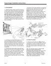
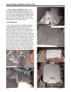
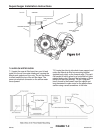
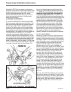
8.2 Locate the rubber sleeves and the front cross
over tube. Check the inside of the cross over tube
for debris - clean if necessary. Running a rag
through the pipe pulled by a strong wire is a good
way to do this. Install the cross over tube between
the idle air manifold (dummy throttle body now on
the intake manifold) and the supercharger dis-
charge manifold. If you find the rubber sleeves
hard to slip over their respective landings, use
some spray light oil such as WD40, which dries off
to lubricate the situation. Do not use gasoline prod-
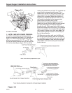
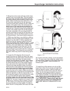
ucts or pure silicone products. The best technique
for installing the cross over tube involves putting
the 2.75” diameter rubber sleeve on the super-
charger manifold and the 2.5” diameter sleeve on
the cross over tube, and attach both with clamps.
Then install the cross over tube, starting at the
supercharger end first.
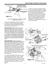
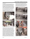
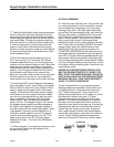
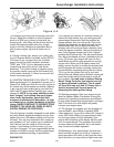
8.3 If you have cruise control, route the factory
vacuum line from the cruise control back to its orig-
inal position, being careful to tie-wrap it away from
the engine belts or radiator fans. Remove the steel
spacer from one of the mounting grommets on
your stock Mazda air box. Use this 13/16” long
spacer and the 6mm x 25mm hex head bolt sup-
plied to secure your cruise control brace to the air
filter base. The bolt will go vertically through the
cruise control leg brace and into the small ledge
with a threaded hole on the air filter base.
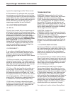
8.4 Once the cross over tube is installed correctly,
double-check all your pipe and tube connections.
There should be no loose ends or connections. Do
not over tighten any hose clamps, but ensure that
they are snug. Double check your supercharger
belt for correct tension. If the cross over tube is
pressing too hard against your upper radiator
hose, you can remove 3/4” to 1” from the radiator
end of the hose to allow for more clearance, if you
wish. You are now ready to start your engine.
8.5 First, crank your engine for a few seconds with
the “FUEL INJ” relay still removed from step 1.1.
Confirm that the supercharger belt stays on and
that no other parts have been left unattended to.
8.6 Reinstall the “FUEL INJ” relay. Complete step
8.7 before starting your engine.
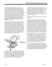
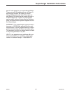
8.7 CLEARANCES
IMPORTANT! MAKE SURE THAT YOU HAVE AT
LEAST 3/4” INCH CLEARANCE BETWEEN ANY
ENGINE MOUNTED COMPONENT AND ANY
BODY MOUNTED COMPONENT. CRITICAL
AREAS: BYPASS ACTUATOR TO BRAKE LINES
(VERY CRITICAL - The engine “rocks” strongly to
the driver’s side upon deceleration. If clearance is
too tight, your brake lines can be gently deformed
away from the super-charger bypass actuator by
hand. ) SUPERCHARGER OUTLET MANIFOLD
TO AIR FILTER (INCLUDING CLAMPS) ALL VAC-
UUM LINES TO THROTTLE SPOOL AND CABLE
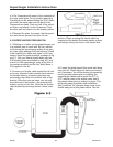
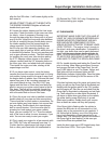
8.8 For trouble shooting and testing the PowerCard
prior to driving, follow these procedures. Unscrew
and remove the back of the PowerCard. You will
see 3 LED lights in a row. The Green, Yellow, and
Red lights are fuel enrichment lights and MIL
(Malfunction Indicator Lights) lights. Read the lights
and refer to the following to find the source of the
MIL problem.
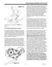
If the box has been wired for power and ground cor-
rectly you will see the Green light is illuminated and
flashing with the ignition switch in the “On” position
and the engine off. Start the car and check that the
Green light is illuminated continuously and not flash-
ing. There should be no other lights illuminated. If
you have no lights when you power up the vehicle,
you either have a power (Red wire) or ground
(Black wire) problem. Double check your connec-
tions at these two wires until they test properly.
If the Green light is flashing after the vehicle is
started, the Blue wire is not connected to a fuel
injector wire or the connection is not complete. If
the Yellow light is flashing, one of the Gray wires
has a bad connection or is not connected to an
injector wire. The Yellow MIL light will not function if
the Green light is also flashing. In this case you
must fix the Blue wire problem first.
Inside the box is one more LED located away from
the other three LED’s. This is your “Boost
999-156 -13- Revised 1/07
Supercharger Installation Instructions