


4848
PROCEDURE 11 REPLACEMENT PARTS - PANTHER MX - 4
R
E
P
L
A
C
E
M
E
N
T
P
A
R
T
S
P
A
N
T
H
E
R
M
X
4
This Procedure Includes the Following:
Removing/Installing Head Light Assembly
Replacing Tail Light Assembly
Replacing Tail Light Cable
Replacing Disc Brake Assembly
Replacing Disc Brake Shoes
Replacing Hand Brake Assembly
Rmoving/Installing Front Shock Absorbers
Removing/Installing Rear Shock Absorbers
WARNING
After ANY adjustments, repair or service and
BEFORE use, make sure that all attaching hard-
ware is tightened securely - otherwise injury or
damage may occur.
Turn Power OFF and remove key from igni-
tion. Disconnect battery harness from the
motor lead.
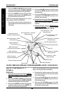
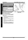
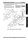
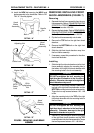
REMOVING/INSTALLING HEAD
LIGHT ASSEMBLY (FIGURE 1)
Removing
1. Separate the front frame assembly from the rear
frame assembly. Refer to TRANSPORTING THE
SCOOTER in PROCEDURE 10 of the Owner’s
Manual, part number 1090132.
2. Flip the front frame assembly onto its side.
3. Pull back the plastic guards on the RED and
BLACK cables connecting the tiller wiring har-
ness to the head light assembly.
4. Disconnect the RED and BLACK cable metal
connectors of the head light assembly from the
RED and BLACK cable metal connectors of the
tiller wiring harness.
5. Remove the two (2) screws, spring washers and
washers securing the front bumper and rubber
spacer onto the front shroud assembly.
6. Remove the front bumper and rubber spacer from
the front shroud assembly.
7. Remove the screw, spring washer and washer
from the plate securing the top of the head light
assembly to the front shroud assembly.
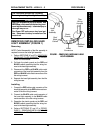
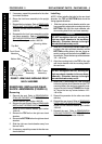
NOTE: Before removing the mounting hardware from
the long screw, be sure to take note of the proper
position for each components.
8. Remove the two (2) self-locking nuts, three (3)
washers, spring washer, spring and the long screw
securing the bottom of the head light assembly to
the bracket on the front frame assembly.
9. Remove the head light assembly from the front
shroud assembly.
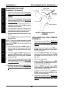
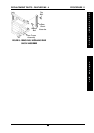
Installing
1. Position the head light assembly through the front
shroud assembly so the mounting holes on the
top and bottom of the head light assembly align
with the mounting holes on the top and bottom of
the front shroud assembly.
2. Position the long screw through the bottom hole in
the front shroud assembly, making sure there is a
washer on either side of the front shroud assembly.
3. Position one (1) nut on the long screw, so that it is
flush against the washer on the inside of the front
shroud assembly.
4. Position the long screw through the bottom hole
on the head light assembly.
5. Position the spring and one (1) washer on the
long screw so that the spring is between the head
light assembly and the bracket on the front frame
assembly.
6. Position the long screw so that it passes through
the bracket on the front frame assembly.
7. Secure the long screw to the bracket assembly
using one (1) spring washer and self-locking nut.
Securely tighten.
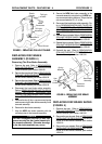
8. Position the plate on the TOP of the head light
assembly making sure the mounting holes in the
plate lines up with the TOP mounting hole in the
front shroud assembly.
9. Secure the plate to the front shroud assembly
using one (1) screw, spring washer and washer.
Securely tighten.
10. Connect the RED cable metal connector of the
head light assembly in the RED cable metal con-
nector of the tiller wiring harness.
11. Connect the BLACK cable metal connector of
the head light assembly in the BLACK cable metal
connector of the tiller wiring harness.
12. Reposition the plastic guards on the RED and
BLACK cables connecting the tiller wiring har-
ness to the head light assembly.