


1313
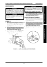
TILLER PROCEDURE 4
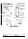
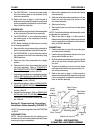
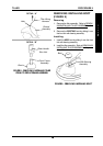
NOTE: To ensure the NEW throttle lever performs
correctly, make certain the tab on the back of the NEW
throttle lever is positioned between the two (2) ends of
the spring on the potentiometer assembly.
(DETAIL “A”)
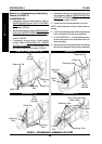
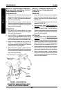
5. Position the NEW throttle lever on the potentiom-
eter assembly.
6. Secure the NEW throttle lever to the potentiometer
assembly using the two (2) NEW socket screws.
Securely tighten.
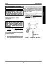
7. Align the four (4) mounting holes in the cable cover
with the four (4) mounting holes in the tiller assembly.
8. Secure the cable cover to the tiller assembly using
the four (4) EXISTING self-tapping screws and
housings. Securely tighten.
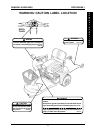
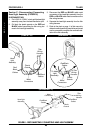
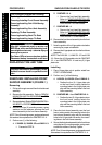
REMOVING/INSTALLING TILLER
ASSEMBLY
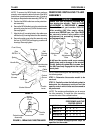
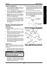
WARNING
Ensure that tiller is properly adjusted be-
fore driving the scooter. Refer to TILLER
ADJUSTMENT in PROCEDURE 8 of the
Owner’s Manual, part number 1090132.
After making ANY tiller angle adjust-
ments and BEFORE use, the tiller MUST
be securely locked into position with
adjustment pin protruding through the
adjustment plate.
T
I
L
L
E
R
FIGURE 3 - REPLACING THROTTLE LEVER
Self
Tapping
Screws
Housings
Socket Screw
Socket
Screw
Throttle
Lever
Self
Tapping
Screws
Housings
Cable
Cover
Spring
Ends
Tab
Tab
Spring
Potentiometer
Assembly
Spring
Front Cover
Handle Bar
DETAIL "A"
See
DETAIL "A"
Throttle
Lever
Potentiometer
Assembly
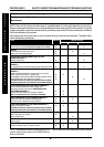
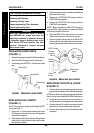
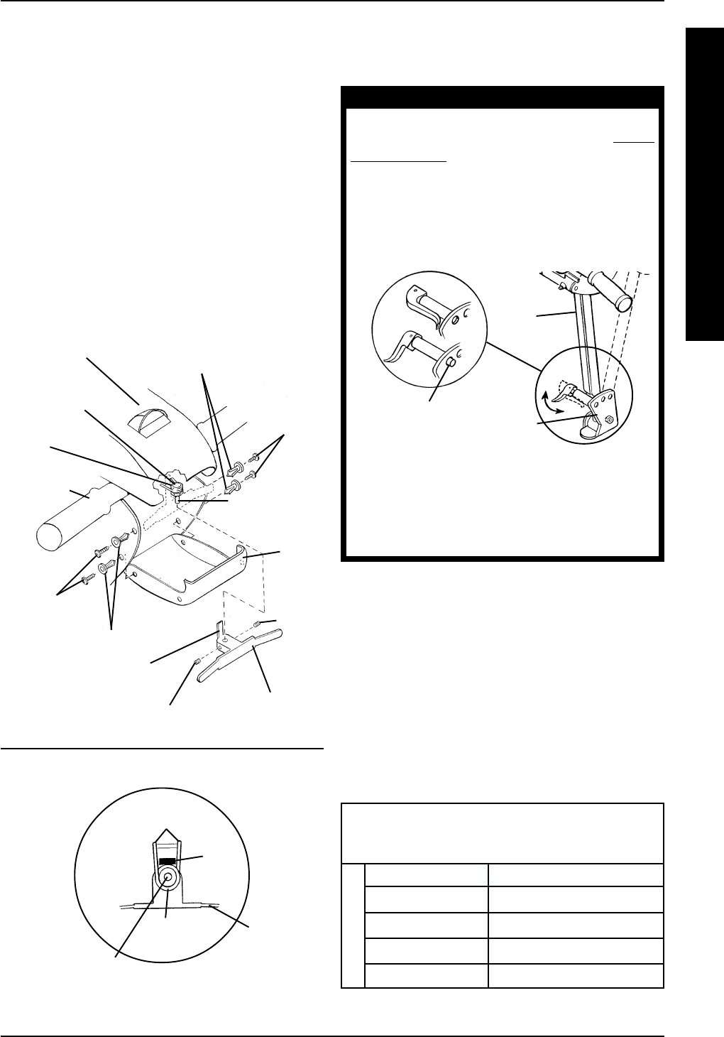
MODEL
SECTIONS TO BE
PERFORMED AND THE
PROPER ORDER
LYNX SX - 3 A D E F
LYNX SX - 3P A D E F
LYNX LX - 3 A D C E F
PANTHER LX - 4 A C D E F
PANTHER MX - 4 A B C D E F
NOTE: When removing the tiller assembly, perform
the following steps:
STEP 1: Determine the scooter model to be
serviced.
STEP 2: Carefully review the following chart to
determine the necessary sections and the
specific order in which these sections need to
be performed.
NOTE: The sections outlined below are to remove
the tiller assembly. To install the tiller assembly,
reverse the order of the outlined sections.
STEP 3: Perform the appropriate steps as
specified for the model.
Tiller
Adjustment
Plate
Adjustment
Pin
A fall from the scooter could occur causing
bodily injury and/or damage to the scooter.
Gently, push/pull against tiller to ensure that
the tiller is securely engaged into the adjust-
ment plate.
Tiller