2222
PROCEDURE 5 SHROUD/FORK/WHEELS/TIE RODS
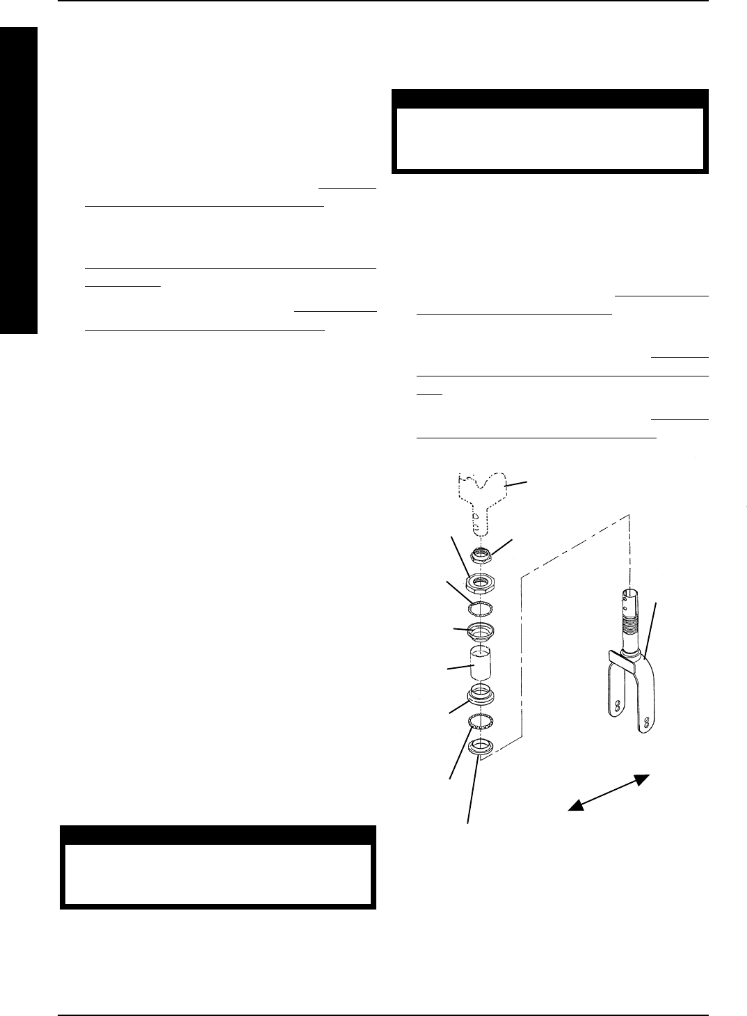
REMOVING/INSTALLING FORK
WITH BEARING ASSEMBLY
(FIGURE 2)
NOTE: This procedure applies to the LYNX SX - 3,
LYNX SX - 3P and the LYNX LX - 3 ONLY.
Removing
1. Remove the tiller assembly. Refer to REMOV-
ING/INSTALLING TILLER ASSEMBLY in PRO-
CEDURE 4 of this manual.
2. Remove the front shroud assembly. Refer to
REMOVING/INSTALLING FRONT SHROUD
ASSEMBLY in PROCEDURE 5 of this manual.
3. Remove the front wheel. Refer to
REMOVING/
INSTALLING THE FRONT WHEELS in PRO-
CEDURE 9 of the Owner’s Manual, part number
1090132.
4. Remove the bearing gap nut from the front fork.
5. Remove the TOP bearing bushing from the TOP
bearing housing.
6. Remove the TOP bearing from the TOP bearing
housing.
7. Slide the front fork, BOTTOM bearing and BOT-
TOM bearing bushing away from the front frame
assembly.
8. Remove the TOP and BOTTOM bearing hous-
ings from the front frame assembly.
Installing
1. Secure the TOP and BOTTOM bearing housing
onto the front frame assembly.
NOTE: Before installing the front fork, be sure it is
facing the proper direction.
2. Slide the front fork with the BOTTOM bearing
and the BOTTOM bearing bushing through the
mounting hole in the front frame assembly.
3. Slide the TOP bearing over the top of the front fork
and into the TOP bearing housing.
CAUTION
DO NOT overtighten the TOP bearing bush-
ing. Otherwise, damage to the front fork as-
sembly may occur.
4. Secure the TOP bearing bushing by threading it
into the TOP bearing housing. Torque the TOP
bearing bushing between 26 - 39 in./lbs.
CAUTION
DO NOT overtighten the bearing gap nut.
Otherwise, damage to the front fork assem-
bly may occur.
5. Secure the bearing gap nut by threading it into
the front fork. Torque the bearing gap nut be-
tween 217 - 243 in./lbs.
NOTE: When reinstalling the front wheel, replace the
EXISTING hardware with the NEW hardware supplied.
6. Reinstall the front wheel. Refer to REMOVING/IN-
STALLING THE FRONT WHEELS in PROCEDURE
9 of the Owner’s Manual, part number 1090132.
7. Reinstall the shroud assembly. Refer to
REMOV-
ING/INSTALLING FRONT SHROUD ASSEM-
BLY in PROCEDURE 5 of this manual.
8. Reinstall the tiller assembly. Refer to
REMOV-
ING/INSTALLING TILLER ASSEMBLY in PRO-
CEDURE 4 of this manual.
Bottom
Bearing
Bushing
Bottom
Bearing
Bottom
Bearing
Housing
Top Bearing
Housing
Top
Bearing
Front
Frame
Assembly
Top
Bearing
Bushing
Bearing
Gap Nut
Front Fork
Facing
Proper
Direction
FIGURE 2 - REMOVING/INSTALLING FORK
WITH BEARING ASSEMBLY
S
H
R
O
U
D
/
F
O
R
K
/
W
H
E
E
L
S
/
T
I
E
R
O
D
S
Front Frame Assembly
Front of
Scooter
Back of
Scooter


