


2525
REPLACING TIE ROD ASSEMBLY
NOTE: This procedure applies to the PANTHER LX
- 4 and the PANTHER MX - 4 ONLY.
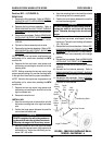
Panther LX - 4 (FIGURE 5)
1. Remove the tiller assembly. Refer to REMOV-
ING/INSTALLING TILLER ASSEMBLY in PRO-
CEDURE 4 of this manual.
2. Remove the shroud assembly. Refer to
REMOV-
ING/INSTALLING SHROUD ASSEMBLY in
PROCEDURE 5 of this manual.
3. Remove the front wheels. Refer to
REMOVING/
INSTALLING THE FRONT WHEELS in PRO-
CEDURE 9 of the Owner’s Manual, part number
1090132.
4. Position the front frame assembly onto its side.
5. Remove the front axle assembly. Refer to
REMOV-
ING/INSTALLING FRONT AXLE ASSEMBLY,
PANTHER LX - 4 in this procedure of this manual.
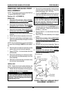
6. Remove the two (2) hex cap screws and self-lock-
ing nuts securing the steering shaft to the U - plate
on the tie rod assembly.
7. Remove the U - plate and the tie rod assembly
from the steering shaft.
8. Remove the bearing gap nut from the steering
shaft.
9. Remove the TOP bearing bushing from the TOP
bearing housing.
10. Remove the TOP bearing from the TOP bearing
housing.
11. Remove the steering shaft, BOTTOM bearing
and the BOTTOM bearing bushing from the
BOTTOM bearing housing.
12. Remove the TOP and BOTTOM bearing hous-
ings from the front frame assembly.
13. Secure the NEW TOP and BOTTOM bearing
housing onto the front frame assembly.
14. Slide the NEW BOTTOM bearing and the NEW
BOTTOM bearing bushing onto the steering
shaft.
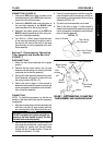
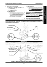
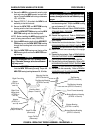
NOTE: Before installing the NEW steering shaft, be
sure it is in the proper direction (FIGURE 5).
S
H
R
O
U
D
/
F
O
R
K
/
W
H
E
E
L
S
/
T
I
E
R
O
D
S
15. Slide the NEW steering shaft with the NEW
BOTTOM bearing and the NEW BOTTOM bear-
ing bushing into the front frame assembly.
16. Slide the NEW TOP bearing over the top of the
NEW steering shaft and into the NEW TOP bear-
ing housing.
CAUTION
DO NOT overtighten the TOP bearing bush-
ing. Otherwise, damage to the tie rod assem-
bly may occur.
17. Secure the NEW TOP bearing bushing by thread-
ing it into the NEW TOP bearing housing. Torque
the NEW TOP bearing bushing between 26 - 39
in./lbs.
CAUTION
DO NOT overtighten the bearing gap nut. Oth-
erwise, damage to the tie rod assembly may
occur.
18. Secure the NEW bearing gap nut by threading it
into the NEW steering shaft. Torque the NEW
bearing gap nut between 216 - 243 in./lbs.
19. Align the two (2) mounting holes in the NEW U-
plate on the tie rod assembly with the two (2)
mounting holes in the NEW steering shaft.
20. Secure the NEW U-plate and the tie rod assem-
bly to the NEW steering shaft using the two (2)
NEW hex cap screws and self-locking nuts.
Torque the NEW self-locking nuts between 112 -
138 in./lbs.
21. Reinstall the front axle assembly. Refer to
RE-
MOVING/INSTALLING FRONT AXLE ASSEM-
BLY, PANTHER LX - 4 in this procedure of this
manual.
22. Return the front frame assembly to the upright
position.
23. Reinstall the front wheels. Refer to
REMOVING/
INSTALLING THE FRONT WHEELS in PRO-
CEDURE 9 of the Owner’s Manual, part number
1090132.
24. Reinstall the front shroud assembly. Refer to
RE-
MOVING/INSTALLING FRONT SHROUD AS-
SEMBLY in PROCEDURE 4 of this manual.
25. Reinstall the tiller assembly. Refer to
REMOV-
ING/INSTALLING TILLER ASSEMBLY in PRO-
CEDURE 3 of this manual.
PROCEDURE 5SHROUD/FORK/WHEELS/TIE RODS