


5252
PROCEDURE 11 REPLACEMENT PARTS - PANTHER MX - 4
R
E
P
L
A
C
E
M
E
N
T
P
A
R
T
S
P
A
N
T
H
E
R
M
X
4
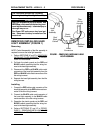
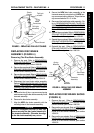
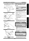
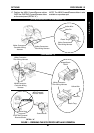
REPLACING HAND BRAKE
ASSEMBLY (FIGURE 6)
1. Remove the bolt securing hand brake assembly
to the handle bar. Refer to DETAIL “A”.
2. Unscrew the adjusting nut from the cable lock
and hand brake assembly. Refer to DETAIL “B”.
3. Align the slit in the cable lock with the brake cable,
and remove the cable lock. Refer to DETAIL “C”.
4. Align the slit in the adjusting nut with the brake
cable, and remove the adjusting nut. Refer to
DETAIL “C”.
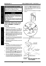
NOTE: Note the position of the the hand brake as-
sembly before removing for proper reinstallation.
5. Slide the hand brake assembly toward the tiller
until there is slack in the brake cable.
6. Maneuver the brake cable through the two (2)
slits in the hand brake assembly until the brake
cable is free from the hand brake assembly (DE-
TAIL “D”).
7. Remove the hand brake assembly from the
handle bar.
8. Position the NEW hand brake assembly onto the
handle bar.
NOTE: In order to perform the next step, the NEW
hand brake assembly should be positioned close
enough to the tiller so that there is approximately
two (2) inches of slack in the brake cable.
9. Maneuver the brake cable through the two slits in
the NEW hand brake assembly, making sure the
ball at the end of the brake cable is in the proper
position in the brake housing. Refer to DETAIL “D”.
10. Slide the NEW hand brake assembly away from
the tiller, until it is in the original mounting position.
11. Align the slit in the NEW adjusting nut with the
brake cable, and position the NEW adjusting nut
on the brake cable. Refer to DETAIL “C”.
12. Align the slit in the NEW cable lock with the brake
cable, and position the NEW cable lock on the
brake cable. Refer to DETAIL “C”.
13. Screw the NEW cable lock into the NEW adjust-
ing nut and hand brake assembly. Refer to DE-
TAIL “B”. Securely tighten.
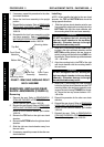
4. Disconnect the hand brake cable assembly. Re-
fer to
REMOVING/INSTALLING TILLER AS-
SEMBLY, SECTION “B” - DISCONNECTING/
CONNECTING HAND BRAKE CABLE ASSEM-
BLY in PROCEDURE 4 of this manual.
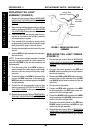
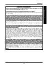
5. Remove the self-locking nut and washer secur-
ing the brake arm to the cam.
NOTE: Save the spring for reuse when installing the
NEW disc brake shoes.
6. Remove the spring securing the two (2) disc brake
shoes to the brake disc.
7. Remove the two (2) disc brake shoes.
8. Position the two (2) NEW disc brake shoes on
the disc brake and around the cam.
9. Secure the NEW disc brake shoes to the disc
brake using the EXISTING spring.
10. Position the brake arm so the two (2) mounting
holes in the brake arm align with the cam.
CAUTION
DO NOT overtighten the self locking nut se-
curing the brake arm to the cam. Otherwise,
damage to the brake arm may occur.
11. Secure the brake arm to the cam using the EX-
ISTING self-locking nut and washer. Torque the
self-locking nut between 86 - 122 in./lbs.
12. Reconnect the hand brake cable assembly. Re-
fer to
REMOVING/INSTALLING TILLER AS-
SEMBLY, SECTION “B” - DISCONNECTING/
CONNECTING HAND BRAKE CABLE ASSEM-
BLY in PROCEDURE 4 of this manual.
13. Reinstall the rear wheels. Refer to
REMOVING/IN-
STALLING THE REAR WHEELS in PROCEDURE
9 of the Owner’s Manual, part number 1090132.
14. Reinstall the rear shroud. Refer to
REMOVING/IN-
STALLING THE REAR SHROUD in PROCEDURE
9 of the Owner’s Manual, part number 1090132.
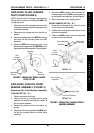
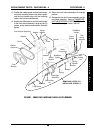
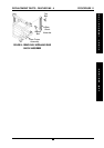
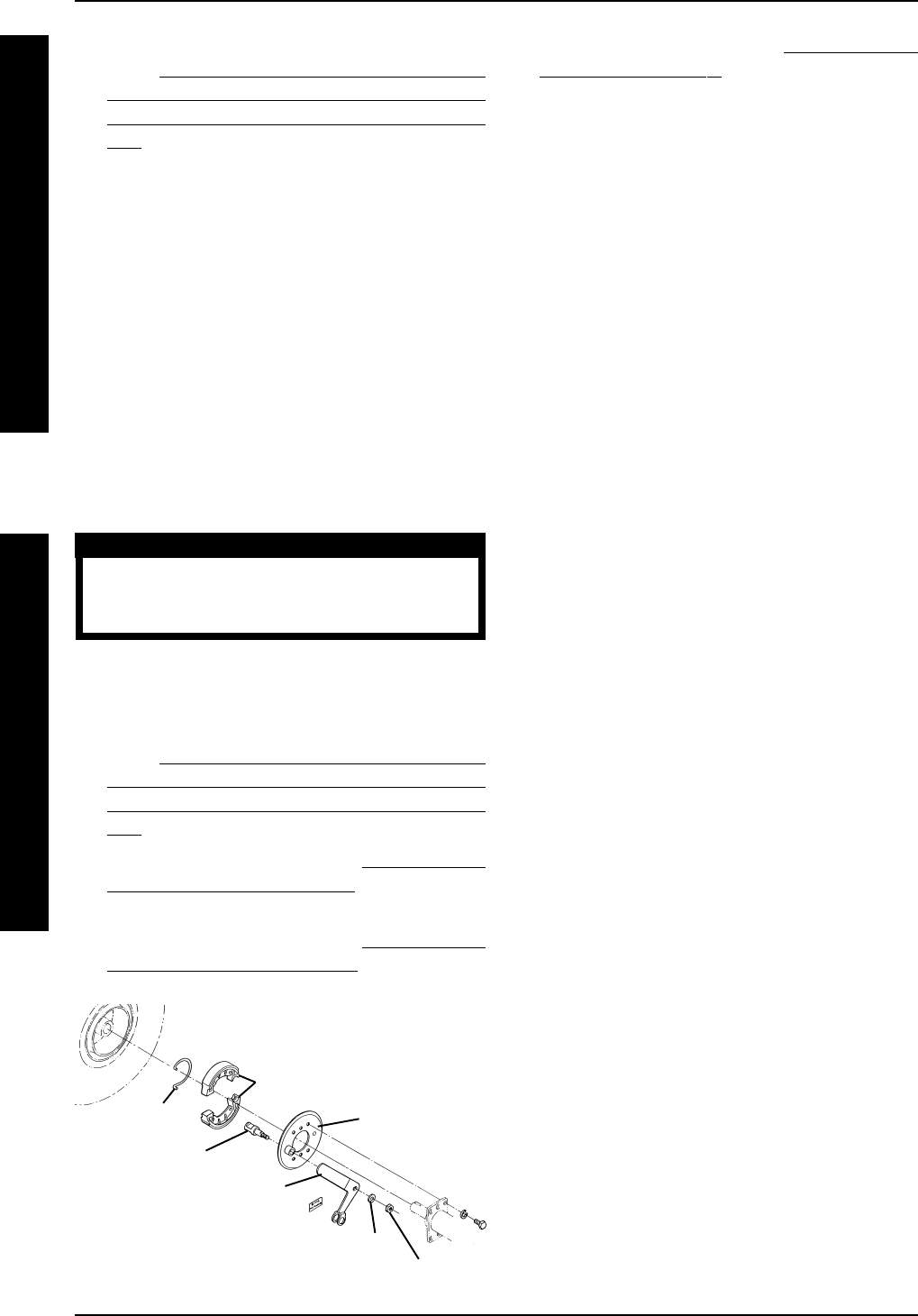
FIGURE 5 - REPLACING DISC BRAKE ASSEMBLY
Brake Arm
Self-locking nut
Washer
Cam
Spring
Disc Brake Shoes
Disc Brake
15. Reinstall the seat. Refer to REMOVING/IN-
STALLING THE SEAT in PROCEDURE 5 of the
Owner’s Manual, part number 1090132.