


3737
REMOVING/INSTALLING
CONTROLLER
Disconnecting/Connecting Controller
Wires (FIGURE 1)
DISCONNECTING.
1. Remove the seat. Refer to REMOVING/IN-
STALLING THE SEAT in PROCEDURE 5 of the
Owner’s Manual, part number 1090132.
2. Remove the rear shroud. Refer to
REMOVING/
INSTALLING THE REAR SHROUD in PROCE-
DURE 9 of the Owner’s Manual, part number
1090132.
3. Remove the transaxle assembly. Refer to
RE-
MOVING/INSTALLING TRANSAXLE ASSEM-
BLY in PROCEDURE 6 of this manual.
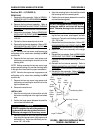
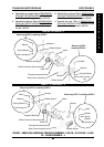
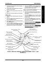
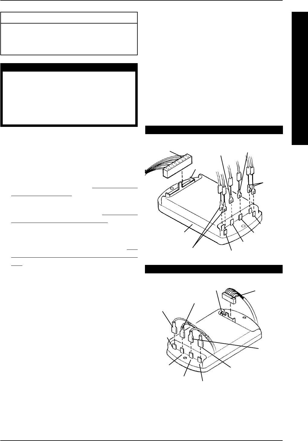
4. Disconnect the following from the controller (FIG-
URE 1):
A. The RED and WHITE connectors from the
slot marked “B+” on the controller.
B. The BLACK and GREEN connectors from
the slot marked “B-” on the controller.
C. The BLACK connector from the slot marked
“M+” on the controller.
D. The RED connector from the slot marked
“M-” on the controller.
E. The housing of the main control wiring har-
ness from the slot marked “P2” on the con-
troller.
This Procedure Includes the Following:
Removing/Installing Controller
Removing/Installing Controller Harnesses
Replacing Circuit Breaker
WARNING
After ANY adjustments, repair or service and
BEFORE use, make sure that all attaching hard-
ware is tightened securely - otherwise injury or
damage may occur.
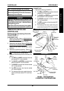
Turn Power OFF and remove key from ignition.
Disconnect battery harness from the motor lead.
CONTROLLER
C
O
N
T
R
O
L
L
E
R
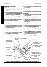
CONNECTING.
1. Connect the following (FIGURE 1):
A. The RED and WHITE connectors to the slot
marked “B+” on the controller.
B. The BLACK and GREEN connectors to the
slot marked “B-” on the controller.
C. The BLACK connector to the slot marked
“M+” on the controller.
D. The RED connector to the slot marked “M-”
on the controller.
E. The housing of the main control wiring har-
ness to the slot marked “P2” on the controller.
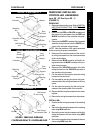
FIGURE 1 - DISCONNECTING/
CONNECTING CONTROLLER WIRES
PANTHER MX - 4
“P2”
Slot
Main
Control
Housing
Red
Connector
Black
And
Green
Connectors
“B-” Slot
“M+” Slot
“M-” Slot
“B+” Slot
Red And White
Connectors
Black
Connector
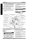
ALL MODELS EXCEPT PANTHER MX - 4
“B-” Slot
“P2” Slot
Black And
Green
Connectors
Black
Connector
Red
Connector
Main Control
Housing
Controller
“B+” Slot
“M+” Slot
“M-” Slot
Red And White
Connectors
PROCEDURE 7