


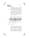


Display The display is a 1-line by 32-character 5x7 dot
matrix alphanumeric display. A photocell is located
in the top left corner of the front panel display. The
photocell automatically controls the light intensity
of the display LEDs from low brightness at night to
high brightness during daylight operation.
Annunciators Several annunciators are used to help indicate the
operating modes of your SL60. The TX (Transmit)
annunciator is lighted whenever you are
transmitting. If the avionics bus drops below 9
VDC, the SL60 will not transmit. An LED will be
lighted above the WPT/COM, NAV, SYS, or MSG
keys when they are pressed. An “s” normally
appears to the left of the Standby frequency. An
“m” will appear to the left of the Standby frequency
when you are using the Monitor function.
TX - Transmit (SL60)
s - Standby Frequency (SL60)
m - Monitor Mode (SL60)
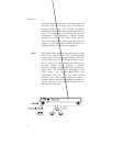
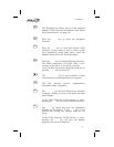
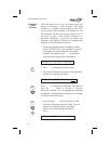
Relative Bearing Indicator
The Relative Bearing Indicator indicates an
approximate bearing to a waypoint or airspace
relative to the aircraft’s current Track when your
current ground speed is more than 5 knots. The
following illustration describes the bearing range
for each arrow.
MNOPQR\T
23º to
67º
68º to
112º
113º
to
157º
158º
to
202º
203º
to
247º
248º
to
292º
293º
to
337º
338º
to
22º
3
Introduction