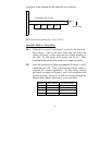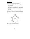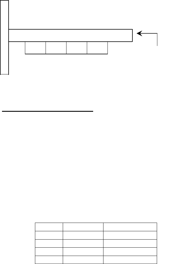
Locations of the switches for the Microflo are as follows:
F
A
C
E
19
P
L
A
T
E
SW4 SW3 SW2 SW1
Component side of board
Board Edge
Each switch has 16 positions, 0-9, A, B, C, D, E, F.
Operation Mode vs. Entry Mode
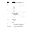
FE: If Switch 1 is set to F and Switch 2 is set to E, the unit is in
Entry Mode. This is the only mode that will allow the
setting of Group 1 values onto the non-volatile memory of
the unit. In this mode, both groups can be set. Once
installed in the aircraft, this mode is no longer accessible.
FF: Once the settings have been programmed, Switches 1 and 2
should be set to FF. This is the Operation Mode, which is
required for normal operations. In this mode, settings
previously recorded for Groups 1 and 2 will be utilized, and
not the switches. Group 2 can still be accessed through the
Manual Entry Mode, but Group 1 is not accessible.
Switch Entry Mode Operation Mode
1 F F
2 E F
3 0 0
4 0 0


