


27
Reference
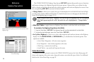
Sonar Tab Settings
• Water Type— since sound waves travel through ‘Fresh’ and ‘Salt’ water at different rates, it is
necessary to select the ‘Water Type’ to ensure accurate readings on the unit.
• Depth Number— controls the efficiency of the digital depth update rate.’ Fast Update’ will update
quicker and is recommended for low-noise, deeper water (>50 ft.). ‘Auto’ is best for shallow water
or high noise areas, will have a slower screen update and is best used if you travel a wide variety of
depths.
If the unit is unable to track the bottom for any reason, the digits in the depth window will
flash on and off to alert you that the unit is not tracking the bottom.
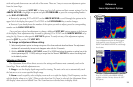
• Dual Frequency Display— allows you to show 200kHz and 50kHz data either together or split on
the display. Choose ‘Merge’ to show both and ‘Split’ to separate the 200/50kHz data. Dual frequency
mode combines both frequencies to get the best coverage area and contour/depth readings. When
the unit is set to ‘Dual’ and the Dual Frequency Display is set to ‘Merge’, the appearance of the fish
symbols (and simulated arches) will change. Fish returns from the center of the beam (200kHz) will be
solid (or narrow arches), but the returns from the edges of the beam (50kHz) will be hollow (or wide
arches).
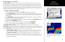
• Scale— controls the depth ‘Scale’ displayed vertically along the right side of the chart. The depth
‘Scale’ can be configured to display four different ways: as an ‘Overlay’, in the ‘Corners’, with ‘Basic’ or
‘No Scale’.
• Color Bar— shows a gradient scale of the current Target Level setting (see page 30).
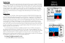
• Flasher— with the ‘Flasher’ active, a graphic Flasher representation will be displayed on the far right
side of the chart. This graphic Flasher displays structure and bottom returns much the same as a true
Flasher. You may find this feature particularly useful when using ‘Fish Symbols’.
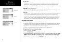
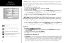
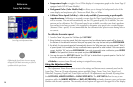
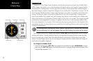
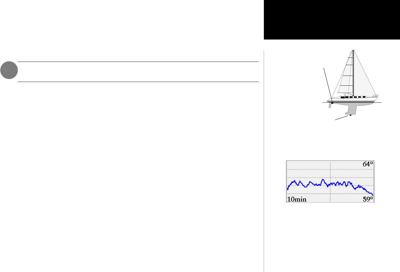
• Keel Offset— allows you to offset the surface reading for the depth of a keel. This makes it possible to
measure depth from the bottom of your keel instead of from the transducer’s location. Enter a posi-
tive number to offset for a keel. It is also possible to enter a negative number to compensate for a large
vessel that may draw several feet of water. The ‘Keel Offset’ will be reflected in the depth reading.
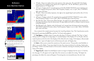
• Map Split Sonar Detail— controls Map Page sonar split range scale. ‘Full Range’ will show the entire
scale of 2X or 4X right side split of the Sonar Page on the Map Page and data fields.
‘Maximum Detail’ will display what is shown on the left side of a split Sonar Page on the Map Page and
data fields.
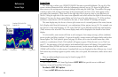
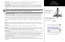
You may display a Temp Log in a data field to
show a plot of the transducer temperature read-
ing over a specified period of time.
Transducer at Surface
Enter (+) positive
number to show depth
from bottom of keel
Transducer at Bottom of Keel
Enter (-) negative number to show
depth from surface
Keel Offset