


96
Appendix A
Wiring and Interfacing
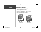
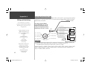
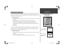
Connecting the Power/Data Cable
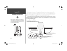
The power/data cable connects the GPSMAP 178C to 10-35 volt DC system and provides interface
capabilities for connecting external devices. The color code in the diagram below indicates the appro-
priate harness connections.
Interfacing
The following formats are supported for connection of external devices: Garmin proprietary Dif-
ferential GPS ( DGPS), NMEA 0183 version 3.01, RTCM SC-104 input (version 2.0).
The following are the sentences for NMEA 0183, version 3.01 output:
Approved sentences— GPBWC, GPRMC, GPGGA, GPGSA, GPGSV, GPGLL, GPBOD, GPRMB, GPRTE,
GPVTG, GPWPL and GPXTE. Sonar— SBDDBT, SDDPT, SDMTW, and SDVHW Proprietary sen-
tences— PGRME, PGRMZ, and PSLIB.
(red) + 10-35 VDC
(black) - Ground (Power/Data)
(blue) Port1 Data OUT
(brown) Port 1 Data IN
(white) Port 2 Data IN
(green) Port 2 Data OUT
(yellow) Alarm Low
To Transducer
To Unit
Beacon
Receiver or
DSC VHF
Autopilot/
NMEA Device
DC
Power Source
RXD +
RXD -
RX+
TX+
Alarm Relay
100ma max
coil current
Note: During a typical installation,
only the Red and Black wires are used.
The other wires do not have to be con-
nected for normal operation of the unit.
Replacement fuse: AGC/3AG - 2.0 Amp
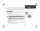
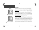
(Cable View)
Pin 16 - Brown (RX COM 1)
Pin 17 - Blue (TX COM 1)
Pin 13 - White (RX COM 2)
Pin 14 - Green (TX COM 2)
Pin 11 - Yellow (Alarm)
Pin 15 - Red (DC Positive)
Pin 18 - Black (Ground)
Complete information concerning
NMEA & RTCM formats and
sentences is available for purchase
from NMEA at:
NMEA
Seven Riggs Avenue
Severna Park, MD 21146
U.S.A.
410-975-9425
410-975-9450 FAX
www.nmea.org
Radio Technical Commission For
Maritime Services (RTCM)
1800 Diagonal Road, Suite 600
Alexandria, VA 22314-2480
U.S.A.
703-684-4481 (Info Only)
703-836-4229 FAX
www.rtcm.org
You can download a copy of Garmin's
proprietary communication protocol from the
Help and Support section of our web site at
www.garmin.com.
GPSMAP178CManual.indd 96 3/19/2004, 3:10:59 PM