


98 GPSMAP 188/188C Sounder Owner’s Manual
APPENDIX > CONNECTING THE POWER/DATA CABLE
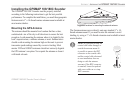
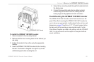
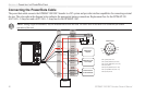
Connecting the Power/Data Cable
The power/data cable connects the GPSMAP 188/188C Sounder to a DC system and provides interface capabilities for connecting external
devices. The color code in the diagram below indicates the appropriate harness connections. Replacement fuse for the GPSMAP 188
AGC/3AG - 2 Amp fuse and a AGC/3AG - 5 Amp fuse for the GPSMAP 188C.
NOTE: During a typical installation, only the Red and Black wires are used. The other wires do not have to be connected for normal
operation of the unit.
100 ma
Max Coil Current
PIN 13 (white) NMEA IN (Com 2 RX)
PIN 14 (green) NMEA OUT (Com 2 TX)
PIN 15 (red) Power
PIN 16 (brown) NMEA IN (Com 1 RX)
PIN 17 (blue) NMEA OUT (Com 1 TX)
PIN 18 (black) Ground
PIN 11 (yellow) Alarm Low
Pin 11
Pin 15
Pin 13
Pin 14
Pin 18 Pin 16
Pin 17