


Av. Kit Install. Manual
190-00026-00 Rev. Q
Page 9
SECTION 3 INSTALLATION PROCEDURE
3.1 INSTALLATION ACCESSORIES
The following installation accessories are available:
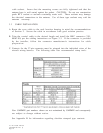
ANTENNA AND RACK OPTIONS
010-10040-01 GA 56 LOW PROFILE ANTENNA KIT (Stud-mount GA 56 antenna, mounting hardware,
no cable)
010-10040-02 GA 56 FLANGE MOUNT ANTENNA KIT (Flange-mount GA 56 antenna, mounting hardware,
no cable)
011-00059-00 MOUNTING RACK w/CONNECTOR
310-00006-00 RG-58A/U CABLE
320-00003-00 15 FT. LOW-LOSS AVIATION ANTENNA EXTENSION CABLE w/RIGHT ANGLE BNC CONN.
320-00003-02 30 FT. LOW-LOSS AVIATION ANTENNA EXTENSION CABLE w/RIGHT ANGLE BNC CONN.
325-00014-00 GPS 100 to GPS 150 WIRING HARNESS ADAPTER
330-00087-00 CONNECTOR, BNC, MALE, CLAMP
011-00313-01 CONNECTOR (J1 only)KIT
The mounting rack is required for approved installations. The following hardware is required for installation of
the mounting rack, but is not provided:
#6-32 Flat Head Screw (4 ea.) #6-32 Self-locking Nut (4 ea.)
Cable and two BNC connectors are required to make the antenna cable, or it can be fabricated by the installer
from materials meeting the requirements of paragraph 2.3.
DATA BASE OPTIONS
010-10038-00 MEMORY CARD - AMERICAS DATABASE
010-10038-01 MEMORY CARD - INTERNATIONAL DATABASE
010-10038-02 MEMORY CARD - WORLDWIDE DATABASE
010-10032-03 MEMORY CARD - USER
MISCELLANEOUS OPTIONS
190-00048-00 GPS 150 PILOT'S GUIDE
190-00048-01 GPS 150 QUICK REFERENCE GUIDE
330-00067-00 GPS 1.57542 GHZ NOTCH FILTER
362-00010-00 WALL CHARGER - 110/220VAC
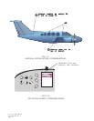
3 . 2 ANTENNA INSTALLATION
The GA 56 Antenna outline and footprint dimensions are shown in Figures 3-1 and
3-2.
A. Using the backing plate as a template, mark the location of the mounting holes and
the through hole for coax cable. Drill or punch the holes.
B. The antenna installation must provide adequate support for the antenna considering
a maximum drag load of 5 lbs. for the GA 56 antennas (at subsonic speed). Install
a doubler plate to reinforce thin skinned aircraft. Observe guidelines for
acceptable installation practices as outlined in AC 43.13-2A.
C. Seal the antenna and gasket to the fuselage using a good quality electrical grade
sealant. Use caution to insure that the antenna connector is not contaminated