


Av. Kit Install. Manual
190-00026-00 Rev. Q
Page 11
3 . 4 RACK INSTALLATION
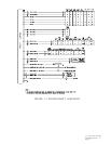
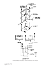
A. Figure 3-4 shows outline dimensions for the aviation rack. Install the rack in a
rectangular 6.320" x 2.000" hole in the instrument panel. Exercise caution when
installing the rack into the instrument panel. The rack is designed to facilitate
removal of the GPS 150 for portable use. Deformation of the rack may make it
difficult to install and remove the GPS 150.
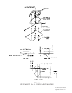
B. Install the rack in the aircraft panel using four #6-32 countersunk screws and four
self-locking nuts. The screws are inserted from the inside through the holes in
the sides of the rack (see Figure 3-5).
3. 5 GPS 150 INSTALLATION AND REMOVAL
The GPS 150 is installed in the rack by sliding it straight in until about 1 inch short
of the final position. A 3/32 inch hex drive tool is then inserted into the access hole
at the bottom of the unit face. Rotate the hex tool clockwise while pressing on the
left side of the Bezel until the unit is firmly seated in the rack. It may be necessary
to insert the hex drive tool into the access hole and rotate the mechanism 90° counter-
clockwise to insure correct position prior to placing the unit in the rack.
To remove the unit from the rack, insert the hex drive tool into the access hole on the
unit face and rotate counter-clockwise until the unit is forced out about 3/4 inch and
can be freely pulled from the rack.
Be sure not to over tighten the unit into the rack. The application of hex drive tool
torque exceeding 15 in*lbs can damage the locking mechanism.
3.6 PLACARD
After completing the installation, a placard stating that the GPS 150 is limited to VFR
use must be installed on the panel in clear view of the pilot. The placard may be
Garmin p/n 161-00024-00 as supplied with the unit, or a suitable equivalent.
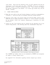
SECTION 4 CHECKOUT PROCEDURE
The GPS 150 ground test procedure incorporates a series of four (4) display pages to
test CDI/flag, OBI, annunciator, and power functions of the unit. These pages can
be selected by ensuring the flashing cursor is off and rotating the outer knob either
direction. To change data on the displayed test page, depress the CRSR key and the
cursor will begin flashing on the first selectable field on the page. The inner knob will
change data on the selected field. The ENT key or the outer knob will advance to the
next field on the page. Pressing the CRSR key again will stop the current field from
flashing, allowing the outer knob to select the next test page (see Chapter 2 of the GPS
150 Pilot's Guide for more information on page and data selection).