


Av. Kit Install. Manual
190-00026-00 Rev. Q
Page 7
SECTION 2 INSTALLATION CONSIDERATIONS
Careful planning and consideration of the suggestions in this section are required to
achieve the desired performance and reliability from the GPS 150.
2.1 ANTENNA CONSIDERATIONS
2.1.1 SATELLITE VISIBILITY
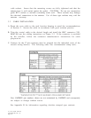
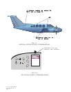
The GPS 150 GA 56 Antenna must be mounted on top of the aircraft. For best
performance select a location with an unobstructed view of the sky above the aircraft
when in level flight. Figure 2-1 illustrates a typical antenna installation.
For rotorcraft, locate the GA 56 antenna:
1) As far from the main rotor hub as possible. This reduces the percentage of time
the blade blocks the antenna.
2) As far below the blade surface as possible if installing the antenna under the blade.
This reduces signal distortion caused by the blades.
2.1.2 NOISE SOURCES
The antenna should be located at least 3 ft from transmitting antennas such as VHF
Comm, HF transmitter, DME, Transponder, and Radar. Cabling for the GPS 150
should not be routed near components or cabling which are sources of electrical noise.
2.1.3 ELECTRICAL BONDING
No special precautions need to be taken to provide a bonding path between the
antenna and the aircraft structure.
2.1.4 ANTENNA LIMITATIONS
GARMIN'S GA 56 Antennas are recommended for installations where the airspeed of
the aircraft will be subsonic.
2.1.5 VHF COMM INTERFERENCE
On many panel-mounted aircraft the VHF COMM radiates strong harmonics from the
unit and the antenna. If the antenna is found to be the problem, a 1.57542 GHz notch
filter (GPN 330-00067-00) may be installed in the VHF COMM coax, as close to the
COMM as possible. If the box is found to be radiating, the following can be done:
1) Place the antenna as far from the VHF COMM unit and antenna as
possible.