


Av. Kit Install. Manual
190-00026-00 Rev. Q
Page 22
APPENDIX A INSTALLATION DETAILS FOR BEECH V35B
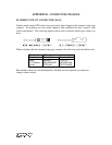
1.0 INTRODUCTION
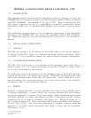
This appendix provides airframe specific information which is necessary to install the
GARMIN GPS 150 navigation system in the Beech Bonanza Model V35B in accordance
with STC SA00066WI. See Appendix C for copy of STC. When so installed, the GPS
150 system is approved for use as a supplementary navigation system under Visual
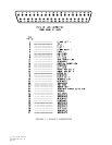
Flight Rules (VFR) only. A functional block diagram of the system is shown in Figure
A-1.
The information provided herein is to be considered supplemental to the information
contained in the GARMIN GPS 150 Aviation Kit Installation Manual, P/N 190-00026-
00. Within this appendix, the base document will be referred to as the "Installation
Manual".
2.0 INSTALLATION INSTRUCTIONS
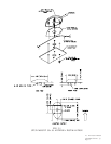
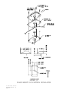
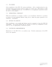
2.1 ANTENNA
The GPS 150 antenna is to be installed on top of the cabin on the aircraft centerline
at fuselage station 130. Figure A-2 illustrates the proper antenna positioning. Refer
to section 2.1 of the Installation Manual for general antenna mounting requirements.
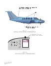
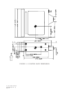
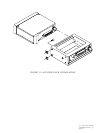
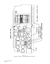
2 .2 AVIATION RACK INSTALLATION
The GPS 150 aviation rack is to be installed in the instrument panel radio rack as
shown in figure A-3. The controls and display of the GPS 150 must be readily visible
to the pilot when seated at the controls.
To install the aviation rack, position it in the instrument panel in the desired position,
assuring that the front is not twisted out of square. Match drill the flanges on the radio
rack to the installation holes on the GPS 150 aviation rack. Using 4 each #6-32 screws
and self locking nuts, attach the aviation rack to the aircraft panel. For additional
information, refer to the Installation Manual.
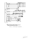
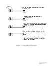
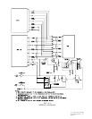
2.3 WIRING
Fabricate an appropriate cable to connect the GPS 150 aviation rack to 28VDC power,
a message annunciator, a remote switch (for selecting between GPS and standard
navigation equipment), a transfer switch with integral white, illuminated annunciators
with black markings (to control and indicate the status of the remote switch). Wiring
connections are to be made in accordance with Figure A-4. Breaker locations are to
be as shown in Figure A-3. Route and connect the wiring in accordance with Advisory
Circular AC-43.13-2A. After the wiring installation is complete, carefully check the
operation of all flight controls throughout their range to assure that no operational
interference exists.