


Av. Kit Install. Manual
190-00026-00 Rev. Q
Page 5
SECTION 1 GENERAL DESCRIPTION
1.1 INTRODUCTION
This manual describes the physical, mechanical, and electrical characteristics and
the installation requirements for the GPS 150 Aviation Kit.
After installation of the GPS 150 system, FAA Form 337 must be completed by an
appropriately certificated agency to return the aircraft to service.
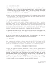
1.2 TECHNICAL CHARACTERISTICS
The GPS 150 offers the versatility of fixed installation in a panel mounted aviation rack
as well as complete portability.
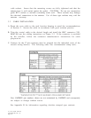
1.2.1 PHYSICAL CHARACTERISTICS
Width: 6.25 Inches
Height: 2 inches
Depth: 5.65 inches
GPS 150 Weight: 2.14 lbs.
GA 56 Antenna Weight: 4 oz.
Aviation Rack Weight: 14 oz.
Max Air Speed: Subsonic
(Structural rating for antenna)
1.2.2 OPERATIONAL CHARACTERISTICS
Operating Temperature Range: -20
o
C to +55
o
C
Humidity: 95% non-condensing
Altitude Range: -1,500 to 50,000 ft.
Power Input: 10 to 33 VDC, 5 watts Max.
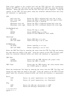
1.2.3 INTERFACES
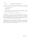
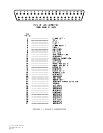
The GPS 150 provides interfaces to various general aviation instruments. Figure 1-
1 defines the function of each pin on the 37 pin DSUB connector located at the back
of the rack. Figure 1-2 depicts the interconnects between the rack and other
instruments. The following interfaces are provided.
CDI: Capable of driving up to three 1000 ohm parallel
(Pins 1 and 5) loads, +150 millivolts full scale deflection with a
maximum output of +300 millivolts.
To/From: Capable of driving up to three 200 ohm parallel
(Pins 2 and 6) loads, +82 millivolts full scale deflection.
Units with Mod Status 1: +190 millivolts full scale
deflection.