


Av. Kit Install. Manual
190-00026-00 Rev. Q
Page 8
2) Replace or clean VHF COMM rack connector to assure good coax ground.
3) Place a grounding brace between the GPS 150, VHF COMM, and ground.
4) Shield the VHF COMM wiring harness.
2.2 RACK CONSIDERATIONS
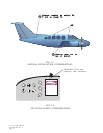
2.2.1 ACCESSIBILITY
Plan a location which gives the pilot complete and comfortable access to the entire
keypad and which is plainly visible from the pilot’s perspective. Check that there is
adequate depth for the rack in the instrument panel. A location away from heating
vents or other sources of heat generation is optimal. Figure 2-2 illustrates a typical
aviation rack installation.
2. 3 CABLING AND WIRING
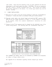
The recommended antenna cable type is M17/155-0001 (RG-58A/U) per MIL-C-17.
Maximum allowable length for this cable type is 40 feet. Other cable types with 50
ohms nominal impedance and longer lengths can be used, provided the installer
insures that the attenuation does not exceed 10dB at 1.5 GHz for the specific
installation. Check that there is ample space for the cabling and mating connectors.
Avoid sharp bends in cabling and routing near aircraft control cables.
2.4 COOLING AIR
Cooling air is not required for the GPS 150, however as with any electronic equipment,
reduced operating temperature can contribute to increased reliability. Additionally,
location of the GPS 150 in a stack of other power dissipating equipment can produce
unacceptably high ambient air temperatures around the unit. A 5/8 inch diameter
air fitting is provided on the rear of the mounting rack for the purpose of admitting
cooling air under such conditions.
2.5 ANNUNCIATORS
If the installation includes any electrical interface with other flight instruments, an
annunciator may be required. Refer to current FAA directives.
2. 6 EXTERNAL ALTITUDE INPUT
Pressure altitude input from an external source may benefit GPS 150 system
performance during times of minimal satellite coverage or poor satellite geometry.
Provisions for RS-232 compatible serial altitude input are described in the Interfaces
section (Section 1.2.3) of this manual.