


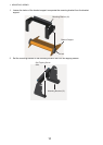
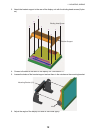

1. MOUNTING, WIRING
14
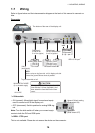
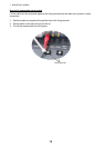
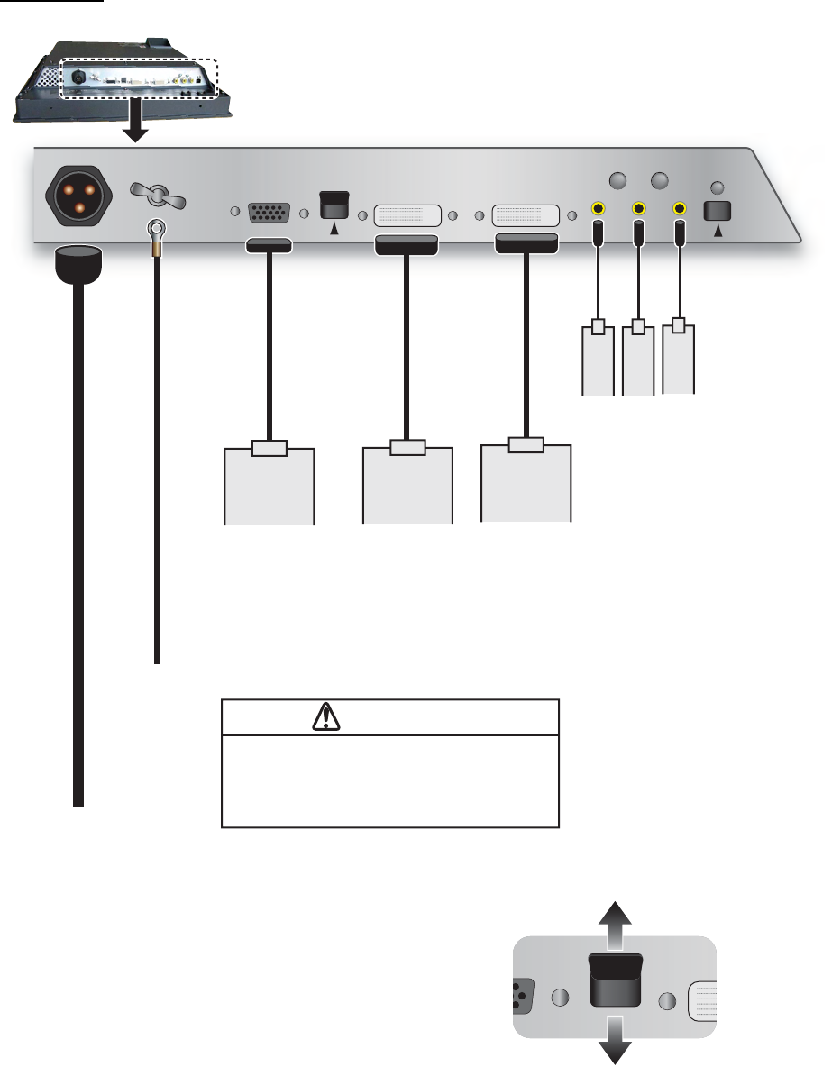
1.7 Wiring
Refer to figure below and the interconnection diagram at the back of this manual to connect ca-
bles.
Connector
*
1
: Slide switch
• ON (upward): Allow digital signal from external equip-
ment to control on/off of the display unit.
• OFF (downward): Set this position for analog RGB sig-
nal.
Note: Turn the slide switch off when you connect equip-
ments to both the DVI and RGB ports.
*
2
: BRILL CTRL port
This is not available. Please do not remove the sticker on the connector.
CAUTION
NOTE:
Attach a crimp-on lug (inner dia. ø 4) for display unit side.
Connect the ground cable as short as possible.
To ground terminal on hull
If the power is 24 VDC, replace the 10 A
fuse with the 5 A fuse (supplied). And
then attach the fuse label on the fuse
cover.
Slide switch*
1
Slide switch*
1
The bottom of the rear of the display unit
12-24 VDC
IV-8 sq
(local supply)
IV-8 sq
(local supply)
MJ-A3SPF0017-050ZC
(5 m, standard supply)
MJ-A3SPF0017-050ZC
(5 m, standard supply)
RGB signal
3COX-2P-6C
5 m/10 m (option)
RGB signal
3COX-2P-6C
5 m/10 m (option)
MODEL 1833C series
FSV-30
FCV-30
FCV-1200L
MODEL 1833C series
FSV-30
FCV-30
FCV-1200L
Digital signal
DVI-D/D SINGLELINK
5 m/10 m (option)
Digital signal
DVI-D/D SINGLELINK
5 m/10 m (option)
FAR-21x7 㫊㪼㫉㫀㪼㫊
FEA-2107㩷㫊㪼㫉㫀㪼㫊
FCR-2107㩷㫊㪼㫉㫀㪼㫊
MFD8/MFD12/MFDBB
FAR-21x7 㫊㪼㫉㫀㪼㫊
FEA-2107㩷㫊㪼㫉㫀㪼㫊
FCR-2107㩷㫊㪼㫉㫀㪼㫊
MFD8/MFD12/MFDBB
CCD camera
DVD recorder
CCD camera
DVD recorder
Composite signal
cable
Composite signal
cable
BRILL CTRL port*
2
BRILL CTRL port*
2
Upward: Default setting
(Slide switch ON)
Upward: Default setting
(Slide switch ON)
Downward
(Slide switch OFF)
Downward
(Slide switch OFF)