


7
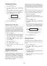
Pin arrangement on the DATA connector is
shown below. For connection at the GPS
navigator, see its manual.
For RS-232C
Pin# Signal Description
1 TXD Output data
2 NC No connection
3 RXD Input data
4 NC No connection
5 RX-H
* Nav Data
(current loop)
6 RX-C
* Nav Data
(current loop)
7 FG Ground
* For auto L/L mode. See page 11.
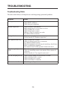
For RS-422
Pin# Signal Description
1 TXD(+) Output data (H)
2 TXD(-) Output data (C)
3 RXD(+) Input data (H)
4 RXD(-) Input data (C)
5 RX-H
* Nav Data
(current loop)
6 RX-C
* Nav Data
(current loop)
7 FG Ground
* For auto L/L mode. See page 11.
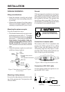
Ground
Connect a ground wire between the ground
terminal at the rear of the receiver and a suit-
able ground point.
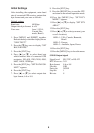
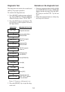
Interface Format
The interface format can be RS-232C or RS-
422 and the default format is RS-422. For
RS-232C, do the following:
1. Disconnect cables at the rear of the re-
ceiver.
2. Unscrews eight screws to remove the re-
ceiver.
3. Disconnect cables connected to the front
panel.
4. Remove printed circuit board from rear
of the receiver.
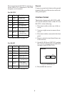
5. On the MAIN Board (08P3192), unplug
the connector plugged into J3 (RS-422)
and plug it into J4 (RS-232C).
08P3192
RS-232C RS-422
J4
J3
Figure 6 MAIN Board
6. Reassemble the receiver.