


6
Receiver Unit Installation
Siting considerations
The receiver can be mounted on a tabletop,
on the overhead or in a panel (requires op-
tional flush mount kit). When selecting a
mounting location keep the following points
in mind;
• Locate the receiver away from rain and
water splash.
• Keep the receiver away from heat
sources.
• Install the receiver out of direct sunlight.
• The viewing angle of the front panel is
±45°.
• Leave at least 100 mm space behind the
receiver and 80 mm space at the sides to
permit easy access to connectors at the
rear and knobs at the sides.
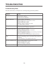
Tabletop or overhead mounting
1. Fix the hanger to the mounting location
with tapping screws.
2. Loosely screw knobs into the receiver.
Set the receiver to the hanger and tighten
knobs.
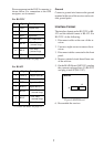
Flush mounting (option)
See outline draing at the end of the manual.
Note: Remove gasket at right and left sides
of receiver before mounting in panel.
FURUNO DGPS BEACON
Gasket
(both sides)
Figure 4 GR-80 receiver unit
Note: For flush mounting, use only the
screws supplied with the flush mount kit to
fix the receiver. Use of other screws may
damage the equipment.
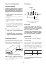
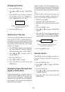
Connections
2A POWER DATA ANT
+-
10.2-31.2 VDC
Fuse
(2A)
Power cable
connector
I/O cable
connector
Antenna ca
b
connector
Ground terminal
Figure 5 Connections on rear
panel of receiver
Power cable
A power cable, complete with connector, is
supplied. Connect the leads to the power
supply; red wire to positive (+) terminal and
black wire to negative (–) terminal.
The receiver does not have a power switch.
We recommend that a switch be dedicated
to the receiver on the mains switchboard.
Antenna cable
Connect the cable to the ANT connector.
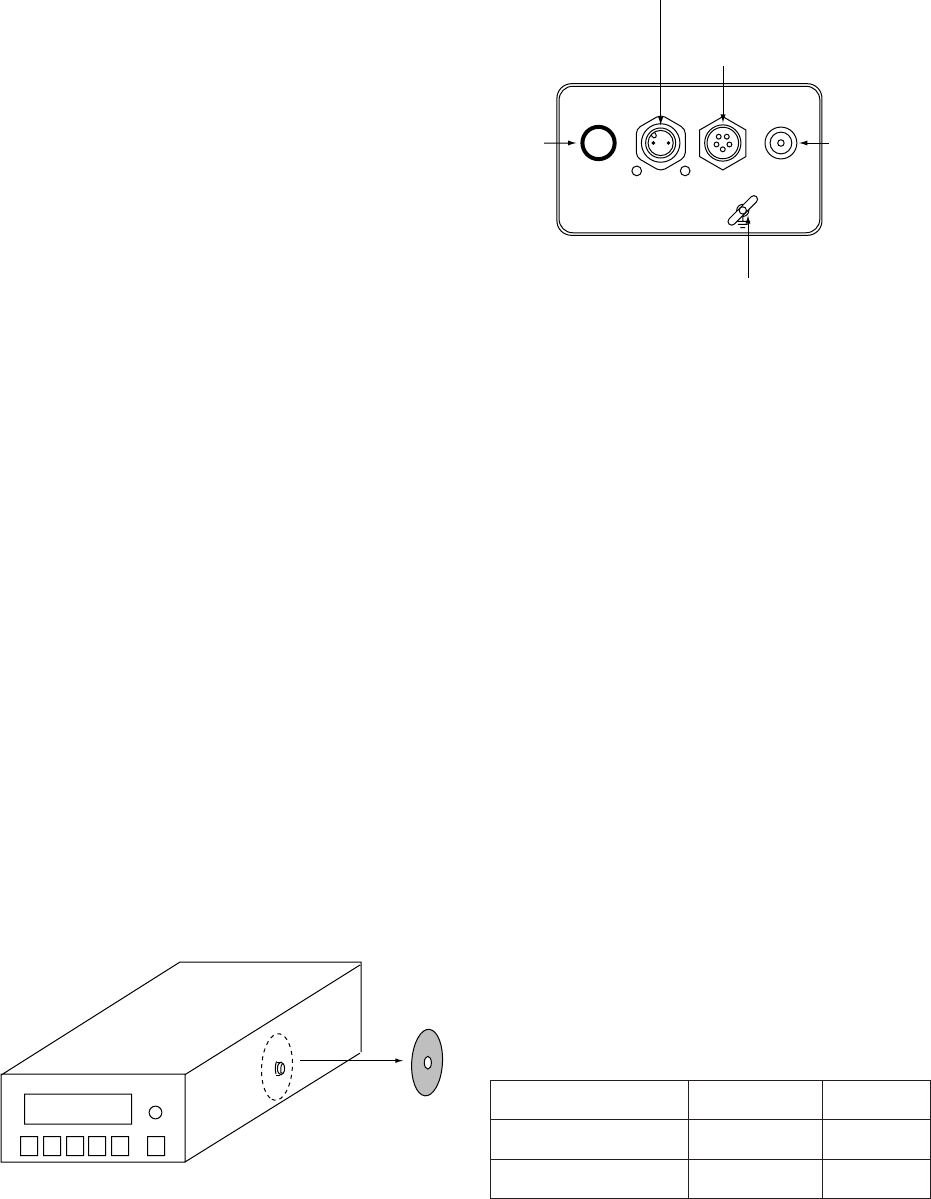
I/O input cable
The 7-pin DATA connector connects the
GPS navigator. A signal cable is supplied
with the navigator; attach the connector
(FM14-7P) supplied with the GR-80 to the
cable. For no signal cable the following
cables are optionally available:
epyTelbaC.oNedoCskrameR
050-3000FPS6A-JM306-711-000m5,P6
050-3000FPS7A-JM037-631-000m5,P7
Note: If the GR-80 is causing interference
to a VHF radiotelephone, follow the proce
dure on page 23.