


APPENDIX TRIDUCER 525ST-PWC/PWD
AP-3
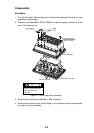
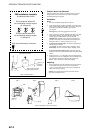
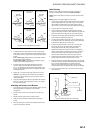
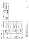
Figure 5. Sensor angle adjustment on transom
11° transom angle
NO SHIM
12-18° transom angle
NO SHIM
2°-10° transom angle 19°-22° transom angle
shim with
taper up
shim with
taper down
parallelparallel parallel
slight
angle
angle
too steep
angle
reversed
YES NONO
YES YESYES
2. To adjust the sensor’s angle relative to the hull, use the tapered
plastic shim provided. If the bracket has been temporarily fastened
to the transom, remove it, Key the shim in place on the back of the
bracket.
2°-10° transom angle (stepped transom and jet boats)—Position
the shim with the tapered end down.
19°-22° transom angle (small aluminum and fiberglass boats)—
Position the shim with the tapered end up.
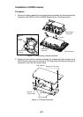
3. If the bracket has been temporarily fastened to the transom,
remove it. Apply a marine sealant to the threads of the two
#10 x 1-1/4” self tapping screws to prevent water seeping into the
transom. Screw the bracket to the hull. Do not tighten the screws
completely at this time.
4. Repeat step 1 to ensure that the angle of the sensor is correct.
Caution: Do not position the sensor farther into the water than
necessary to avoid increasing drag, spray, and water noise and
reducing boat speed.
5. Using the vertical adjustment space on the bracket slots, slide the
sensor up or down to provide a projection of 3mm (1/8”). Tighten
the screws (see Figure 6).
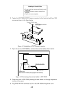
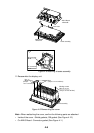
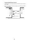
Attaching the Sensor to the Bracket
1. If the retaining cover near the top of the bracket is closed, open it by
depressing the latch and rotating the cover downward
(see Figure 4).
2. Insert the sensor’s pivot arms into the slots near the top of the
bracket.
3. Maintain pressure until the pivot arms click into place.
4. Rotate the sensor downward until the bottom snaps into the
bracket.
5. Close the retaining cover to prevent the accidental release of the
sensor when the boat is underway.
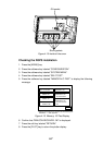
Cable Routing
Route the sensor cable over the transom, through a drain hole, or
thorough a new hole drilled in the transom above the waterline.
Caution: Never cut the cable or remote the connector; this will void the
warranty.
Warning: Always wear safety goggles and a dust mask.
1. If a hole must be drilled, choose a location well above the waterline.
Check for obstructions such as trim tabs, pumps, or wiring inside
the hull. Mark the location with a pencil. Drill a hole through the
transom using a 19mm or 3/4” bit (to accommodate the connector).
2. Route the cable over or through the transom.
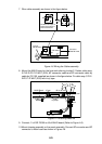
3. On the outside of the hull secure the cable against the transom
using the cable clamps. Position a cable clamp 50mm(2”) above the
bracket and mark the mounting hole with a pencil (see Figure 6).
4. Position the second cable clamp halfway between the first clamp
and the cable hole. Mark this mounting hole.
5. If a hole has been drilled in the transom, open the appropriate slot
in the transom cable cover. Position the cover over the cable where
it enters the hull. Mark the two mounting holes.
6. At each of the marked locations, use a 3mm or 1/8” bit to drill a
hole 10mm (3/8”) deep. The prevent drilling too deeply, wrap
masking tape around the bit 10mm (3/8”) from the point.
7. Apply marine sealant to the threads of the #6 x 1/2” self-tapping
screw to prevent water from seeping into the transom. If you have
drilled a hole through the transom, apply marine sealant to the
space around the cable where it passes through the transom.
8. Position the two cable clamps and fasten them in place. If used,
push the cable cover over the cable and screw it in place.
9. Route the cable to the instrument being careful not to tear the cable
jacket when passing it though the bulkhead(s) and other parts of the
boat. To reduce electrical interference, separate the sensor
cable from other electrical wiring and “noise” sources. Coil any
excess cable and secure it in place with zip-ties to prevent damage.
10. Refer to your echosounder owner’s manual to connect the sensor
to the instrument.
cable cover
cable clamp
50mm (2")
Hull projection
3mm (1/8")
Figure 6. Vertical adjustment and cable routing