


AP-1
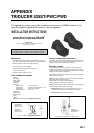
APPENDIX
TRIDUCER 525ST-PWC/PWD
This appendix provides a copy of the installation instructions for AIRMAR triducer. If you
loose the original supplied with the triducer, use this appendix.
INSTALLATION INSTRUCTIONS
Transom Mount Transducer or TRIDUCER
®
Multisensor with Integral Release Bracket
Model P66
U.S. Patents: 4,555,938; 4,644,787; 5,606,253; Des. 334,335
Canadian Patent 1,233,341
IMPORTANT Please read the instructions completely before
proceeding with the installation. These directions supersede
any other instructions in your instrument manual if they differ.
Applications
• Powerboats with outboard, inboard, inboard/outboard, or jet drive.
Not recommended for boats with large or twin screw inboard motor.
• Bracket protects the sensor form frontal impact only
• Good operation up to 44kn (50MPH)
• Orients the sound beam vertically on hulls with a
deadrise angle up to 30°
• Adjusts to transom angles from 2-22°
Tools and Materials Needed
Scissors
Masking tape
Safety goggles
Dust mask
Electric drill
Drill bit for:
Bracket holes 4mm, #23, or 9/64”
Fiberglass hull chamfer bit (preferred), 6mm, or 1/4”
Transom hole 19mm or 3/4” (optional)
Cable clamp holes 3mm or 1/8”
Screwdrivers
Straight edge
Marine sealant
Pencil
Zip-ties
Water-based antifouling paint (mandatory in salt water).
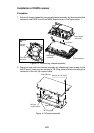
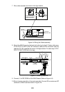
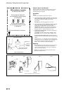
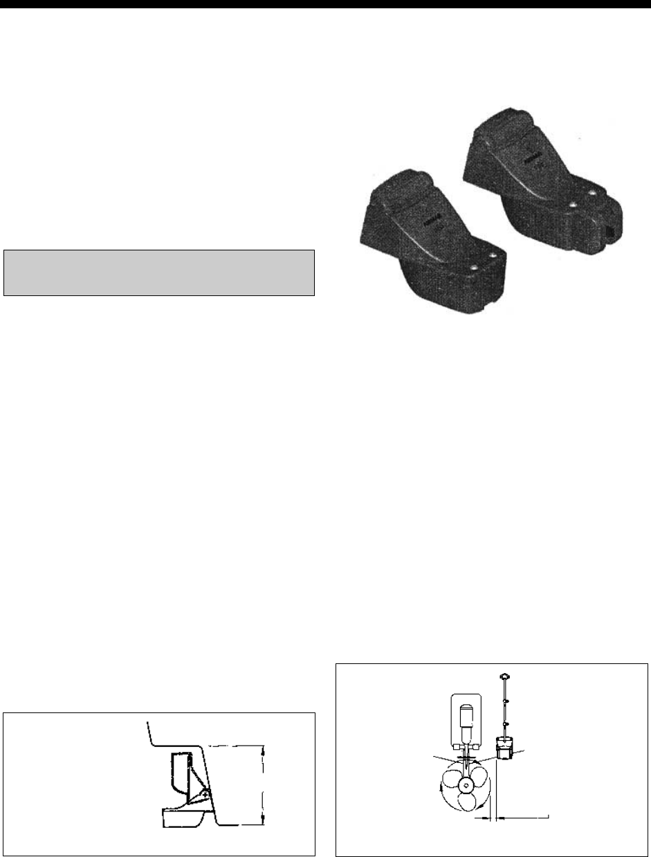
height
Height without
speed sensor
191mm (7-1/2")
Height with
speed sensor
213mm (8-1/2")
Figure 1. Height required at mounting location
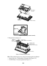
Pre-test for Speed and Temperature
Connect the sensor to the instrument and spin the paddlewheel. Check
for a speed reading and the approximate air temperature. If there is no
reading, return the sensor to your place of purchase.
Mounting Location
To ensure the best performance, the sensor must be submerged in
aeration-free and turbulence-free water. Mount the sensor close to the
centerline of the boat. On slower heavier displacement hulls, positioning
it farther from the centerline is acceptable.
Allow adequate space above the bracket for it to release and rotate the
sensor upward (see Figure 1).
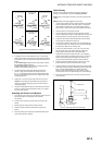
Caution: Do not mount the sensor in an area of turbulence or bubbles:
Near water intake or discharge openings;
Behind strakes, struts, fittings, or hull irregularities;
Behind eroding paint (an indication of turbulence).
Caution: Avoid mounting the sensor where the boat may be supported
during trailering, launching, hauling, and storage.
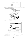
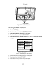
• Single drive boat—Mount on the starboard side at least 75mm
(3”) beyond the swing radius of the propeller (see Figure 2).
• Twin drive boat—Mount between the drives.
75 mm(3")
minimum beyond
swing radius
Figure 2. Mounting location on single drive boat