


4-5
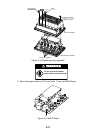
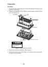
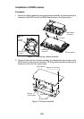
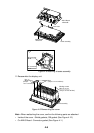
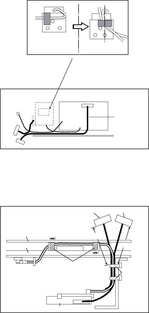
7. Wire cable assembly as shown in the figure below.
Reattach this tape as
shown right after the
DGPS connection.
To J8 of
ANLG Board
GN-7707
J1
GR-7000A
J2
J3
Connector
PH6P-W-L240
J2
Figure 4-6 Wiring the Cable assembly
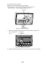
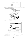
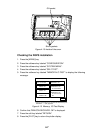
8. Mount the ANLG board on the heat sink referring to step 2. Fasten cable assy.
S.FL2-2LP0.7-D-WHT (250), 8P connector cable and 6P connector cable by
cable tie (CV-100, supplied) as shown in the figure below. Fix cable assy. S.FL2-
2LP0.7-D-WHT (250) with vinyl tape.
J8
ANLG Board
6P connector
GN-7707
Cable
tie
8P connector
40 to 45 mm
10 mm
10 mm
MAIN Board
40 to 45 mm
vinyl tape
Figure 4-7 Attaching cable tie
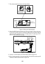
9. Connect J1 of GR-7000A to J8 of ANLG board (Refer to Figure 4-6).
10.Mount chassis assembly on the panel assembly. Connect 8P connector and 6P
connector to Main board as shown in Figure 4-8.