


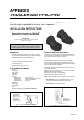
APPENDIX TRIDUCER 525ST-PWC/PWD
AP-2
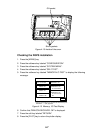
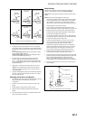
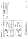
P66 Installation template
for starboard side of boat
Drill at locations labeled "B"
for the following transom angles:
16° through 22°
Drill at locations labeled "A"
for the following transom angles:
2° through 15°
Align arrow with bottom of transom
AA A
BB B
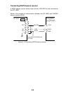
Align template vertically
deadrise angle
slope of hull
parallel to
waterline
Align template arrow with
bottom edge of transom
Figure 3. Template position
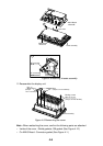
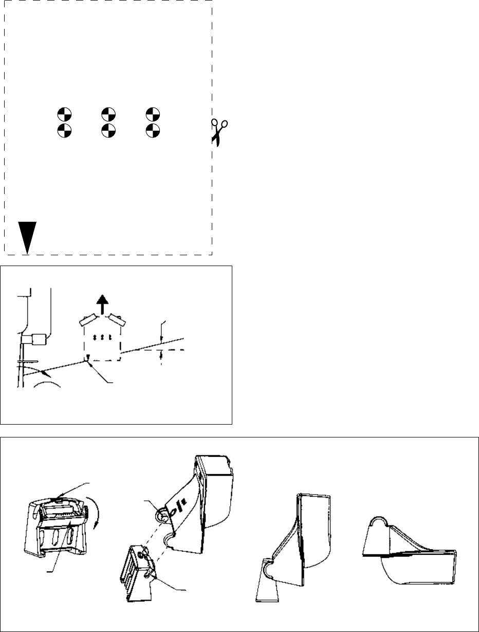
Step 1 Step 4Step 3Step 2
latch
retaining
cover
pivot
arm (2)
slot (2)
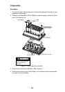
Figure 4. Attaching the sensor to the bracket
Caution: Never Use Solvents!
Cleaners, gasoline, paint, sealants, and other products may contain
strong solvents such as acetone which can attack many plastics
dramatically reducing their strength.
Installation
Bracket
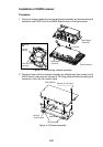
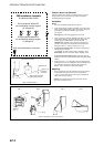
1. Cut out the installation template shown on the left.
2. At the selected location, position the template, so the arrow at the
bottom is aligned with the bottom edge of the transom. Being sure
the template is parallel to the waterline, tape it in place
(see Figure 3).
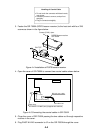
Warning: Always wear safety goggles and a dust mask.
3. Using a 4mm, #23, or 9/64” bit, drill three holes 22mm (7/8”) deep
at the locations indicated. To prevent drilling too deeply, wrap
masking tape around the bit 22mm (7/8”) from the point.
Fiberglass hull—Minimize surface cracking by chamfering the
gelcoat. If a chamfer bit or countersink bit is not available, start
drilling with a 6mm or 1/4” bit to a depth of 1mm (1/16”).
4. If you know your transom angle—The bracket is designed for a
standard 13° transom angle.
11°-18° angle—No shim is required. Skip to “Adjusting”, step 3.
Other angles—The shim is required. Skip to “Adjusting”, step 2.
If you do not know the transom angle—Temporarily attach the
bracket and sensor to the transom to determine if the plastic shim is
needed.
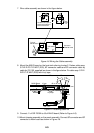
5. Using the two #10 x 1-1/4” self-tapping screws, temporarily screw
the bracket to the hull. Do not tighten the screws completely at this
time. Follow the instructions for “Attaching the Sensor to the
Bracket”, steps 1-4 before proceeding with “Adjusting”.
Adjusting
1. Using a straight edge, sight the underside of the sensor relative to
the underside of the hull. The stern of the sensor should be
1-3mm (1/16-1/8”) below the bow of the sensor or parallel to the
bottom of the hull (see Figure 5).
Caution: Do not position the bow of the sensor lower than the
stern because aeration will occur.