


42/42
SK5W7J-19A361-AA
© Copyright Ford 2005
2W7Z-16A901-AA
Rev Date- 8/29/05
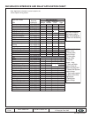
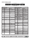
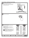
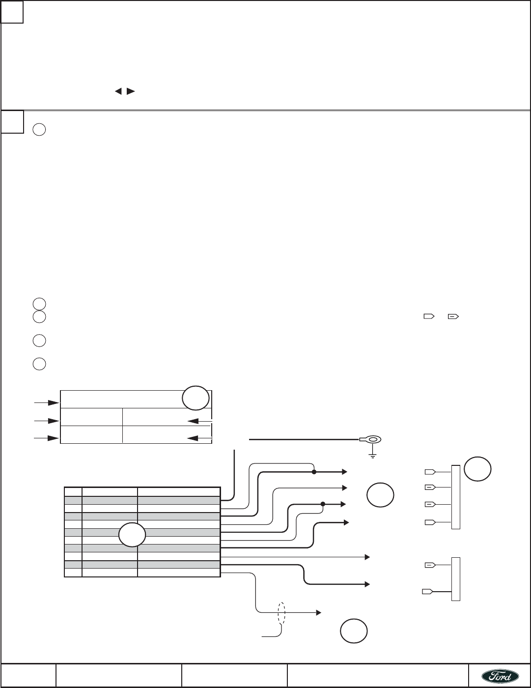
Color Function
A-5 BLACK Ground
A-20 GREEN/VIOLET Door Ajar Switch Input
A-3 BLACK/WHITE Dome Light Output
A-2 BLUE Door Lock Output
A-14 GREEN Door Unlock Output
A-12 LT.GREEN Unlock Switch Sense Input
A-11 WHITE/BLUE Arm Input
C-4 LT GREEN/BLACK Factory alarm disarm output
A-9 BROWN Disarm Input
A-24 BLUE/GREEN Driver Door Unlock Output
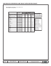
DRIVERS SIDE KICK PANEL
CHASSIS GROUND POINT
IN DRIVERS KICK PANEL
MAKE THIS CONNECTION FIRST!
HARNESS UNDE
R
DRIVERS SIDE
DOOR SILL PLAT
E
Dome Light (BLACK/BLUE)
+
+
DRIVER DOOR
JAMB BOOT
HARNESS
+
Door Lock (PINK/YELLOW)
Door Unlock (PINK/GREEN)
Lock Motor (PINK/BLACK)
Driver Door Unlock Motor
(RED/ORANGE)
Driver Door Ajar Switch
(YELLOW/BLACK)
Cut and tape off if not used
Optional Installation Feature
See Optional connections page
Vehicle (Year/Make/Model)
’02/’03 Explorer Sport / Sport Trac
Equipment or Trim level System(s) applicable to:
w/Factory RKE Deluxe RKE/VSS
Page Revision Date
1 of 4 7/30/02
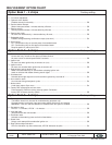
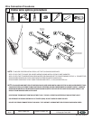
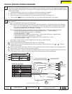
VEHICLE SPECIFIC WIRING DIAGRAMS
This section presents Vehicle/Product specific wiring diagrams are provided for all systems. The diagrams are organized by
vehicle (Year/Model) and by Product. For example, to find a specific wiring diagram for installing a RKE/VSS/RMST system in
a 2002 Explorer Sport:
1. In the Bookmarks pane, click on the “+” symbol to the left of the bookmark for “2002MY”.
2. Click on the “+” symbol to the left of the bookmark for for “Explorer Sport/Sport Trac.
3. Select the system that you are installing in the links revealed under Explorer Sport/Sport Trac.
4. Then using the
buttons in the Acrobat toolbar, you can view the individual pages in the drawing.
1
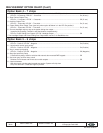
A Title block:
Box 1: Lists applicable vehicle(s) by year/make/model;
Box 2:Lists any vehicle trim level or special equipment required on the vehicle. This will generally be: ALL, w/Factory
RKE or w/o Factory RKE. Note: If you are working on a vehicle with factory RKE, a drawing that lists “w/o RKE”
in this box does not apply to this installation. Conversely, if you are working on a vehicle without factory RKE,
disregard the drawings listing “w/Factory RKE” in this box.;
Box 3:Lists the system or systems covered by this drawing (System name --> Short name used in title block);
• Remote Start System with Deluxe Vehicle Security and Keyless Entry —> RKE/VSS/RMST
• Remote Start System with Keyless Entry —> RKE/RMST
• Remote Start System —> RMST
• Deluxe Vehicle Security System with Keyless Entry —> Deluxe RKE/VSS (shown in graphic below)
• Vehicle Security System with Keyless Entry —> RKE/VSS
• Vehicle Security System for Vehicles Equipped with Factory Keyless Entry —> VSS
• Keyless Entry System —> RKE
Box 4:Page number and total number of pages which make up the complete drawing;
Box 5:Revision date of drawing.
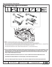
B Lists the systems wires by Connector/Terminal, Wire color, and function.
C Lists the vehicle circuit by the vehicle wire color and circuit polarity - Circuit name (wire color)
+
or
(indicates
vehicle’s circuit polarity).
D List the circuit location in the vehicle. Clicking on the text will open another window showing a color photograph of the
circuit location in the vehicle (internet connection required).
E Optional connections - clicking on the “Optional installation feature” text, will jump to a diagram showing the connection
of the optional circuit. Clicking on the “Go to Previous View” button will return to the original page.
2
B
C
D
E
Box 2
Box 1
Box 4
Box 3
Box 5
A
SK5W7J-19A361-AA