3/42
SK5W7J-19A361-AA
© Copyright Ford 2005
2W7Z-16A901-AA
Rev Date- 8/29/05
READ ME FIRST
For convenience this document uses short names when referring to a particular system or kit. The list below identifies the
short names used herein:
Remote Start System with Deluxe Vehicle Security and Keyless Entry —> RKE/VSS/RMST
Remote Start System with Keyless Entry —> RKE/RMST
Remote Start System —> RMST
Deluxe Vehicle Security System with Keyless Entry —> Deluxe RKE/VSS
Vehicle Security System with Keyless Entry —> RKE/VSS
Vehicle Security System for Vehicles Equipped with Factory Keyless Entry —> VSS
Keyless Entry System —> RKE
Navigating this document can be accomplished by: 1) using the
buttons in the Acrobat toolbar, 2) clicking on the
bookmark links in the bookmark pane to the left. (Clicking on the (+) symbols next to a bookmark will expand that bookmark,
revealing additional selections) or 3) clicking on a topic in the table of contents located on page 2.
The most current version of this document can be accessed at www.mcdistributor.com and/or www.fmcdealer.com. As new/
updated material becomes available, this document will be updated and posted on those sites.
This installation instruction covers the installation of all PowerCode based Convenience/Security and Remote start kits,
therefore follow only the steps that apply to the kit that you are installing. For example, the Securilock interface kits are only
used on systems that include remote start (RMST). Therefore, if you are installing a security only kit, skip the steps pertaining
to the Securilock interface kit.
Vehicle wiring is subject to change. All possible efforts have been taken to ensure that the information contained herein is
accurate as of the revision dates indicated. As such, it is critical that vehicle circuits are tested prior to making any
connections, to ensure that the proper vehicle circuit has been located.
Prior to beginning this installation it is recommended that you lower the drivers door window to prevent locking the keys in the
vehicle.
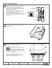
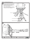
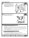
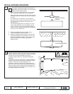
The installation instructions are presented in three sections. The first section (which begins immediately following this page)
contains installation instructions for the systems various components and tips for prepping the systems wiring harnesses.
These steps are presented in a generic format. The procedures for these installation steps are basically the same regardless
of the model vehicle or system that you are working on. The drawings depicted in this section are for reference only and may
not reflect the vehicle on which you may be working.
The second (reference) section contains the system option programming charts and various other reference type information.
The last section presents vehicle specific wiring diagrams for each application. Within the wiring section for each vehicle,
there are separate wiring diagrams for each different system. The vehicle specific wiring drawings are arranged in the
following order:
1. RKE/VSS/RMST & RKE/RMST (in the same drawing) - Typically 4 pages;
2. RMST - 1 page
3. Deluxe RKE/VSS - 3 - 4 pages;
4. RKE/VSS & RKE installation options - 1 page;
5. VSS - Typically 1 page;
6. Pre-load system wiring - 1 page;
7. Fuse placement and vehicle specific programming requirements - 1 page.
Vehicles that are equipped with 100% factory keyless entry will not have the RKE/VSS & RKE drawing. Some drawings will
have blank pages inserted to maintain the page order.
Prior to beginning your first installation of this product it is recommended that you:
1. Thoroughly review and print out the first section;
2. Skim through the reference section to become acquainted with the additional information that is available.
Then, when going through the installation print out the vehicle specific wiring section and use as a reference during the
installation.


